Having had some success in building a DIY equivalent to the USB-COM cable, I started to think about the COM-IP controller. Texecom sell this at great expense. It provides an Ethernet interface from the panel, which allows you to configure the panel over the network rather than having to connect directly to the panel. It also allows you to connect other things in to the panel to provide remote control or get status information from it. The first problem is the price. CTS-Direct have it for just over £90 plus delivery and this seems to be about right. Numerous other retailers have it for the same price although there are some second hand deals on ebay which are a bit better. However this still costs more than the panel did which seems a bit much for such a tiny device:  I have been investigating linking the panel up with other home automation kit (more later) and someone suggested to me that you could use ser2net running on a Raspberry Pi or similar in conjunction with the USB serial connection I already had in order to give the same results. First thing was to see what the serial connection is actually doing, and establish what the parameters for the serial connection are. I used a serial port sniffer to identify this. I tried a few but eventually found ‘Free Device Monitoring Studio‘ which is massive overkill, but does provide the basic functions needed. I ran this whilst connecting to the panel with Wintex. I was hoping to see some comprehensible data but in fact it is clearly encoded. However, I was able to get the serial parameters out which are:
19200 baud, 8 data bits, no parity, 2 stop bits
This is the first time I have ever seen a serial link which uses 2 stop bits – so maybe this is a sneaky trick by Texecom to get you to buy their product. If so then it is fairly easy to get around. The next thing to do is to set up ser2net. It forms part of most Linux repositories, and the Raspberry Pi is no exception. I’ve started with a fairly basic and clean install, booting to the command line. Then I have installed ser2net like so:
apt-get install ser2net
Then plug in the serial cable and it should be recognised and appear as a serial device. You can use the ‘dmesg’ command in Linux to check. I’m using a FTDI 232R device:
[166583.359561] usb 5-1: new full-speed USB device number 2 using ohci-pci
[166583.821660] usb 5-1: New USB device found, idVendor=0403, idProduct=6001
[166583.821673] usb 5-1: New USB device strings: Mfr=1, Product=2, SerialNumber=3
[166583.821680] usb 5-1: Product: FT232R USB UART
[166583.821685] usb 5-1: Manufacturer: FTDI
[166583.821690] usb 5-1: SerialNumber: A9C3JDH1
[166583.927074] usbcore: registered new interface driver usbserial
[166583.927109] usbcore: registered new interface driver usbserial_generic
[166583.927136] usbserial: USB Serial support registered for generic
[166583.936455] usbcore: registered new interface driver ftdi_sio
[166583.936482] usbserial: USB Serial support registered for FTDI USB Serial Device
[166583.936601] ftdi_sio 5-1:1.0: FTDI USB Serial Device converter detected
[166583.936658] usb 5-1: Detected FT232RL
[166583.936662] usb 5-1: Number of endpoints 2
[166583.936665] usb 5-1: Endpoint 1 MaxPacketSize 64
[166583.936669] usb 5-1: Endpoint 2 MaxPacketSize 64
[166583.936672] usb 5-1: Setting MaxPacketSize 64
[166583.939669] usb 5-1: FTDI USB Serial Device converter now attached to ttyUSB0
The next step is to set up ser2net to connect to the USB serial port and convert it to network frames. This is done by putting a line in the configuration file – held in /etc/ser2net.conf. I’ve used this line:
10001:raw:0:/dev/ttyUSB0:19200 8DATABITS NONE 2STOPBITS
‘10001’ is the port number (used later); ‘raw’ means that there is no further processing of the frames; ‘/dev/ttyUSB0’ is the name of the serial device as above; the rest of the line contains the serial parameters we found above. Restart ser2net to re-read the config file, and then you will have in effect a working equivalent of the COM-IP. To make use of it you will need to IP address of the server running ser2net and the port number as above. The most obvious use of this is to use Wintex (the Texecom configuration tool) over the network. Configuring this is the same as for the genuine COM-IP although it is a little obscure. You need to go into ‘Edit Account’ in Wintex: 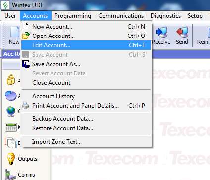 And then select the ‘Panel Details’ tab:
 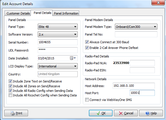 It’s hidden away in the bottom right hand corner under ‘Network Details’ – here you need to enter the IP address of the server, and the port configured in ser2net. Once you’ve done this, you can connect to the panel using the ‘Connect’ button in the Wintex main screen and proceed as normal. So far as I can tell this approach exactly replicates the function of the real COM-IP but at a fraction of the price, or indeed free if you already have a Raspberry Pi or a server lying around. There are some other interesting ideas for making use of this which I’ll come to in future posts.

Great article… but how reliable to do you find the connection? Maybe I need to double check my wiring… have you experienced any connectivity problems?
So far it has been fine, and I’ve not had any problems with the connection. I’ve not really stressed it, but whenever I’ve tried connecting it has worked properly. If you are using a USB connection to the panel do you have any problems connecting directly?
Very useful! Do you know if the android app also works? What security is there? Wintel would be ok on local network and local PC but to be useful I’d want to access it over the net when away. Hence I’d want it to do stuff like https, password, and limit the number of tries (i.e. block IP after x fails for y minutes so password could not be brute forced).
I’ve not tried using the app, but I’m sure it would work. I’m not so sure about security though – I don’t think that Texecom provides anything particularly sophisticated here. If you wanted more security at an IP level, could you perhaps use some rules on a firewall to control access to ports?
What I’ve done with this is functionally equivalent to the Texecom devices, so it might be worth having a look at how they address these issues. However, I don’t think they intend for it to be used over the Internet, but rather over some form of private connection (ie wifi or a direct IP connection over the phone). However if you were able to add some external security to control port access as above I am sure it would work across the Internet. Please let me know what you find!
So what I have so far is that a cheaper solution is to use the comwifi board which is about half the price of the wired lan. However, I’ve had one opinion that the comwifi isn’t as reliable as wired.
I was planning on having a Pi so I’d be tempted to look at interfacing to the Pi serial port (but maybe with some buffers for isolation/level shift).
The app works by having comms with panel. No security other than the normal password. That’s ok for on a local network although it does mean any who know your wifi password could have access to your alarm keypad from outside the house. Maybe the Pi has the serial port off until you go through more security on the Pi.
For true remote access the app can set up tracking of your house IP. I think the way this must work is the app tells the panel (or comip/comwifi?) to regularly ping the Texecom server with your alarm account number. Then the app gets told by the Texecom server if the IP changes. Plus of course you have to open a port on your router to let the internet to the panel. That’s the official way I believe. The better way is to setup a vpn (on the Pi again I guess). Then vpn from phone/tablet to your home network at which point you’ll see the panel on your local network.
BTW the texecom basic app is free (engineer’s app is < fiver). If you have your panel on your local network then it wouldn't cost anything to test the app.
That’s interesting on how the ‘real’ solution works but it does sound rather complicated and if you are exposing your panel to the Internet in any way then it is potentially vulnerable.
I think your idea of a VPN is the best way to go – that’s what I was thinking of before but couldn’t articulate it! That way you are not exposing anything to significant risk and it should be an easy matter to control the panel once the VPN is set up.
I need to have a look at the app. The main thing that’s been stopping me so far is that I’ve been using the COMIP equivalent connection for a home automation link, although in truth I’ve not really got into that either yet and I could spare some time for testing.
I think the logic of the real solution is that you’re just an IP address. A burglar wouldn’t know which house that IP belonged to. But, I seriously doubt the logic of that. Your IP gets sent with everything you do online. It’s a small step to link that to posts, stuff sold online (giving your area), or facebook etc..
Thanks for your info – I have managed to get sim800 working and I have a raspberry pi connected via a pl2303 adapter and ser2net – wintex is working and texecom app on the ipad
Brilliant, glad you’ve got it working.
I have a ComIP board but is causing the system to “frozen” a lot of times… It gets totally unresponsive (app or in the panel) and I must do a physical reset to bring the system online again… It can be my fault, but I’m very disappointed with the ComIP until now…
Are you using an official Texecom ComIP or a home-made one?
If it is an offical one then I think you should send it back because it sounds faulty to me. I have been using my version of the interface for ages now, and I have never once had a lockup like you describe. So I think it is probably a faulty board (or maybe even a faulty panel?). I would suggest trying to get your money back and build one yourself and you will save quite a lot!
I managed to connect to my premier 816 plus but after a few seconds occured a connection problem. Any opinion?!
What sort of interface are you using? I’m less familiar with the the Premier plus panels, I think they are a little older than the Premier Elites. However the basics should still be the same. I would suggest beginning by connecting directly to the panel using USB before doing anything else. If you are using a DIY interface, perhaps try a different serial converter?
Thanks for your reply. I can connect to the panel through the official usbcom conveter. Now with this i am trying to connect using rasberry. Do think that the problem is the conveter? If i will use a pl2303 conveter i will managed to connect with success?? Thanks in advance!
i managed to connect to the panel through the local network, but i can’t connect through internet. port forward is not working. To the site “can you see me” a can see open all other ports that i am using and having forward (for cctv and other applications) but i can’t see port 10001. any opinion?
This sounds like an issue with your router, as you will need to open the port on the router and forward it on the local network to the panel. If it works on the local network then it is working fine. However I’d be a bit careful about doing this as it isn’t secure and in theory anyone could connect to your panel and could even lock you out of it!
Thanks again for your reply. Propably my isp provider has blocked port 10001. Ca i try an another one (8082) to test the remote connection?? Furthermore about safety this is real that the panel can be attacked. Do you hace any suggestion to makethus remote connection safe???
Yes you can try a different port but you will to set this up in Wintex and in the ser2net configuration. The only way to secure it would be to set up a VPN into your home network from outside. An alternative is to use the Texecom apps but I haven’t done this myself as yet
Thanks again for your reply. I will try different port also i wil test texecom applications.but and with applications i think that with this solution the panel will not be safe. Only the official comip provide a secure connection.
Great write up. I use both ComIP and ComWifi in various sites however I was looking at a project similar to this.
Does this only work for Wintex programming or can the board connect out like the ComIP/Wifi for remote signaling? I have played with connecting to the com2 port which is set to ComIP but keep getting repeated garbage (hex 0x98 0xFE bytes) then every so often get ATH0 then ATZ
I believe that this functions in exactly the same way as the real one and so long as the internet connection is set up properly you can get at it remotely. However I’m not quite sure how this works in practice. You can I think use the comgsm equivalent with a data sim yo provide a data connection or else use it (as I have) for and messages. How have you used ComIP for remote signalling before?
I use several ComIP and ComWifi in our sites. They are all configured to communicate with our server which simulates a remote monitoring centre and sends out alerts to staff etc.
I am currently playing with some ESP8266 boards and was hoping to set one up to act like a comwifi at a fraction of the cost (around £8!).
When the com port is set to ComIP it seems to send out various AT commands to configure the module etc. I guess I need to capture the communication and trying and work out what I need to simulate.
It would be great to use an ESP board in this way and I’ve thought about this before. There already are some serial to Wifi modules available from the various Chinese suppliers via ebay which are not too expensive, and I am sure that they would work also but they won’t be as cheap as an ESP. I suppose what you need to do is look at what ser2net does and replicate that as I am sure it is the same process. I wonder if the AT commands are part of that – no doubt it will be possible to work it out from reading the source although that’s beyond my capabilities!
Well ser2net would be pretty simple on the ESP like you have done with the Rapsberry Pi but I am guessing that would only simulate a serial port as though you are connected to the com port with wintext.
My initial testings (crudely hacking together two ftdi serial cables to capture the communication between the panel and ComIP) show various AT commands from the panel to configure the ‘comip’ device. I need to spend a bit more time capturing as the commands from the panel appear to end with just a new line (\n) and I didn’t get chance to dump the raw data but just copy&paste the outputs so a lot of the commands got overwritten on the console.
I will probably write a quick sketch with softwareSerial to capture the serial communication and try and work out the conversation from that.
After that, replicating the ComIP/ComWifi module should be pretty easy
Hi this has been a great project i have it working to a point in so much as i can read info from panel via wintex but can’t write and in the app i can see the panel info time date tec but can’t control it.
with the usb cable plugged into the pc rather than the pi i can read / write to the panel so the lead works fine, any ideas please.
When you say you can read but not write, what is happening in Wintex? Do you get any error messages? I’m a little perplexed by this, in that you would need two way communication to establish the Wintex connection in the first place so I suspect your connection is working fine. I have had trouble with the app myself – I think it is something to do with the various passcodes but I have never had it working reliably. Can you post your ser2net.conf file? Can you see any errors in the syslog on the pi?
I’ve just got this working using a USR-TCP232-T device. http://www.usriot.com/p/ip-modules/ I picked one up for around £8 from ebay along with a separate 12V-5V DCDC converter and configured it as follows:
TCP server
Port 10001
COM settings:19200/8/None/2
Then made the settings in wintex on the edit account details page
Connected it up to a COM port inside the panel and the phone app and wintex connection sprang in to life.
It doesn’t perform as complete COMIP as if you set the ports in the communications options dialog to have a COMIP connected communications fails and you can no longer connect. I assume this means that a number of the COMIP notification features aren’t available?
I need to knock up a plate with this module, the DC-DC and my SIM800 module in it now :o)
Good work! Someone else has done something similar with a Wifi version and I’m going to post about this shortly. I’m not sure about the ports you mention… must have a look at that. I can’t see a reason why what you have done should not duplicate a genuine ComIP.
Please help.i did everything i have read here and no problem at all.with wintex i can read and write with no problem.with texecom app for android i can’t connect. It starts and stops at “checking users panel. ” after that it disconnects.
Any ideas ??? Please…
I think configuring the ports as COMIP must send out some control codes to th factory module that the clone doesn’t know what to do with.
I’ll have a play when I get some more time.
I have now built up the board with the DCDC and modules on it, I’m just trying to figure put how to mount it in the box so that it physically looks nice.
I’m afraid that I have also had no success in getting the app to work. I think that this is something to do with the ‘UDL’ code but I’m not sure. Has anyone else got it working?
It would be interesting to understand exactly what the effect is of not having this option set. I’ve not really looked at getting alerts sent out, so it may well be that’s something to do with it. Wintex certainly does work, and it will need a bit more investigation to work out what’s going wrong. I’ve seen references to the IP board being ‘configured with IP info’ when you set the option, but not quite sure what this means.
I have the app working. Did you set the UDL password to match what is set in the panel? I think the default is 1234.
I then set the user code and user id to set my code and user number from wintex.
Then it just fired up.
I have spent quit a lot of time playing with this now. I think the only thing you can’t do if you don’t enter comip as a setting in the comms page is to get the panel to poll out for notifications and to check ths link is up as per the manual.
Certainly setting the comip option in the config page makes the panel send +++ ATH0 ATZ ATZ then 0x98 0xfe repeatedly. Replying to the AT with OK didn’t seem to get me too far but the panel stopped sending the hex digits.
The Lantronix XPort module on the factory unit has an AT command mode that seems to let you ping addresses and do a fair amount of other stuff as well as set the modules IP address and then flip into data mode. Id be interested to see if anyone else can get some sensible progres by replying to the at commands…
For MATT :
I used the correct udl pass and right user id.with the key application i couldn’t do anything but with engineer application i see error messages …
If you can describe what you did exactly, wich appl you are using and how you program it.
John
I’m using the Texecom v 2.0.5.51 android app.
Try installing the pingtools app and make sure you can ping the ip address of your serial to ethernet interface with the android device.
Then log in to the app, click on my sites and then push and hold on the site to edit it.
On the IP Details Tab I entered the IP address and 10001 port number and clicked stay connected.
Security details I entered the UDL password and left the protected UDL password blank
User area I entered my user code and user id as per wintex
Then clicked back and clicked on the site the finally clicked on Connect to site.
The annunciator on the next screen in the top right then changes from magenta to cyan to blue, clicking on keypad then brings up my keypad…
I would make sure that you are not running wintex connected via the IP interface at this point and that your android app is the only thing that is trying to use your ethernet to serial adaptor.
In Wintex it may also be worth checking that you haven’t got the “Disable Online Keypad Operation” box ticked in the communications options box.
I can’t really offer any more help than that to be honest!
Matt
I have done all you writing….you are great .thanks for all your help.i am not sure for the option you are writing for.i will check and reply.
When i am using the program the smart key function work almost 100 percent. When i am trying to connect via keyboard it writes but before that ,fos a second, it shows me
the right keyboard. It seems that for a second it can read my panel and then losses “something “.i dont know how to explain it…i will try again.
after some days trying i can say….nothing.
with wintex everything perfect.inside -outside house ( lan-wan)
with texecom appl nothing.i have always errors.if anyone has any idea i am open.
only for the possibility of mistake:
1 udl pass its the password i use in wintex for logging in
2 user pass its the pass i put on the keyboard of the alarm
3 user id the id from wintex (00,01,02, etc )
4 port 10001
5 ip : lan the ras pi ip – wan : the ddns i have
for MATT : i don’t have this in my panel (In Wintex it may also be worth checking that you haven’t got the “Disable On line Keypad Operation” box ticked in the communications options box. )
my panel is premier 832 int version 16.12 .i am not sure if i should have that???!!!
for any question or idea please don’t hesitate
Does the keypad in wintex work?
Can you ping the interface using the ping tools app in android?
yes i can ping to the ip.
yes the keyboard works 100%
thank you
i have configure the com port as usb . right or wrong?
After many efforts i manage to make smart key works. I have install texecom keypad version 2.0.5.18
and it works well.i have still problem with keypad. It still gives me errors and i can’t use it.IDEA’ . ???
many thanks to the community .
I hope someone else can find the problem. And please write here for the others who are trying.thanks again
What error messages are you getting, and what sort of problems are there? I’d really like to get to to the bottom of this, I’m sure you are not the only one having trouble with it.
Looking at the Xport manual, it does support ‘modem mode’ but it says that if it receives ATH it will shut down ‘modem mode’ and then drop into normal command mode. We probably need to find the correct response that the panel is expecting, but there are loads of possible combinations. Hmm… what we really need is someone with the genuine article to sniff what is happening when the panel negotiates with the COMIP board. Any takers?
I am very glad to see that you are active abgain 🙂
When i start application the light at the up right cornet start with pink and becomes blue.now its connected
After that if i go to the keypad its shows me ,for a second, what my physical keypad shows and then writes ERROR, ERROR, ERROR and that’s all.with smart key and the version i wrote above i have no problem.i can connect, arm ,part arm and disarm.
Tell me if i can do anything to help you.
Hi all,
Thank you for your great work gw0udm!!
I have got a old Premier 816 panel from my neighbor who is an alarm professional installer.
Initially disapointed this panel did not have any morden communication options I went looking for ways around this, and stumblered on your work.
I have the original USB-COM and have it working with ser2net on a Ubuntu install on my netbook. It is working perfectly with wintex software, but the iOS app is a bit hit and miss.
It will connect most of the time, but when reading out eventlog it gets a little mixed up, it looks like it is missing some control characters or some communications are a bit out of sync.
I have configured ser2net with 19200 baud none 2stopbits
Any suggestions as to why?
Tonight I will try with a different serial converter, and possibly also with a different computer
– my hope is I can get it to run on a $6 A5-V11 OpenWRT router with ser2net:
https://www.aliexpress.com/item/MINI-3G-WIFI-Hotspot-IEEE-802-11b-g-n-150Mbps-USB-Wireless-Router-Portable-Black/32754325511.html
(already have a couple of these and they are great for the price)
Thanks!
Unfortunately I’ve also had problems with the apps. I think this is the main difference between the genuine article and the DIY approach using ser2net. The problem is that there is no way for the panel to know what IP address has been assigned to it. The real interface uses an Lantronix XPort (https://www.lantronix.com/products/xport/) which has some way of communicating via AT commands to tell the panel what the address is. Without this there are a few things which don’t work correctly. I’ve not yet been able to work out the protocol which it uses to set the IP. HOwever… just thinking about it now I wonder if you can set a static IP address in the panel config to address this issue? I will have a delve into the docs and see.
That router looks great too – do let me know how you get on with it, would be a very neat solution.
Sorry for not getting back before.
I finally got the app to work, to some extend. For some reason it seems to be much more stable (but still VERY unstable) when connecting over the internet using 4G and through a forwarded port on my router.
Good enough that I have managed to reverse engineer the protocol, and I have spend the last days making a simple web interface to control the alarm panel and readout the log.
I’m not a programmer, and I wanted to be able to run it all on the small OpenWRT router, so it’s ugly written i pure shell script… but it works!
So with this I think I can finally start using this as my main alarm system. Only thing missing is some way to alarm me. I’m thinking of using a SIP VoIP box to call me, or maybe a 4G router with phone line interface.
The Premier 816 does not support ComGSM unfortunately. What was you using before the ComGSM?
Also I can’t seem to create an “installer account” on texe.com. I never receive the confirmation mail 😦 Any change you can help me with the newest version of wintex?
Yes I also remember seeing a box in wintex where you can configure a static IP address, but I haven’t looked to much in to it, since I loose contact with the panel if I set the com-port to ComIP.
Never mind the wintex software. I tried signing up using my gmail account and it worked.
Guess the Texecom server don’t like my mail server using SPF based greylisting 🙂
Great, glad you’re sorted
The Texecom support forums are pretty good also and another benefit of being a ‘registered installer’. Now if only they would give out free samples!
I need to check the static IP thing when I get the chance.
I’ve not used anything before this, but I do know that you can get boxes which respond to a simple input (which you can trigger from one of the programmable outputs) to dial a number with a fixed message. You can get these on ebay fairly cheaply. I’m sure that you could find other ways of doing this too. You don’t get the detail of zone reporting etc but you will at leasy get a notification when the alarm goes off.
Further to my post above about a little data logging where I was receiving +++ ATH0 ATZ ATZ then 0x98 0xfe repeatedly I have done a little more thinking about this.
The line data rate when I was receiving this was 19200 and looking at page 85 of lantronix xport manual (http://www.lantronix.com/wp-content/uploads/pdf/XPort_UG.pdf) after power cycle you can enter monitoring mode with networking by typing ‘zzz’ at 9600 baud.
If we take the bit stream on the wire for 0x98 0xFE at 19200 we have:
0|00011001|1….1|0|01111111|1
Halving the baud rate (so every pair of digits above count as a single digit) to 9600 and guessing the inter-character spacing this could give:
0|01011110|1
This would be 0x7a which is a lower case ‘z’
From this I believe what happens when COMIP is selected is:
Baud rate 19200
+++
ATH0
ATZ
ATZ
Power cycle the 12V output on the selected COM port
Baud rate 9600
z
z
z
z
z
At this point the module should be in monitoring mode and should respond with the characters ‘0>’
I am not with the kit at the moment but if anyone gets chance it may be worth setting the baud rate to 9600 and firing ‘0>’ at the panel!
Well I have hooked up to the panel at 9600 and it is sending a series of z characters as expected. However sending a ‘0>’ isn’t recognised by the panel.
I’m not just trying to dig through reams of Lantronix Data to figure out exactly what the XPORT module sends in response to the z.
Well I have progressed….
In response to the z’s it would appear that the xport actually sends:
*** NodeSet 2.0 ***
0>
I found this information here: http://ltxfaq.custhelp.com/app/answers/detail/a_id/1660/~/displaying-network-settings-from-dhcp-on-a-cobos-device-server
So I sent that to the panel and in response I then get the following:
G0
S0
According to the Lantronix manual http://www.lantronix.com/wp-content/uploads/pdf/XPort_UG.pdf this is a get configuration command followed by a set configuration.
Next step is to try and get the panel to report the IP address that I have set in WinTex
Brilliant work!
I will get a summary of this up as a new post, it really feels we are getting close to properly replicating the COMIP now.
The Lantronix Module is configured by the alarm control panel when the real module is installed.
Basically the alarm panel will be trying to spew the IP details in to the module to configure it, if it does not get a valid response then the panel may keep trying to initialize the module.
On the Premier Elite range, this is what the “NodeSet” does. You can view the contents of the serial buffer by pressing ZERO when on the COM PORT in the “Com Port Setup” menu.
Press RESET to flush the buffer.
UDL Password NEEDS to be programmed in for the APP to work.
On the Premier Elite Panels it is here:
Eng Code -> (7) UDL/Digi Options -> YES -> (5) UDL Options -> YES -> UDL Password is:
Press NO to edit, type in a 4,5 or 6 digit code of your choice, press YES to save.
This code WILL NOW be used for WINTEX and the APP.
NOT THE ENGINEER CODE.
On the Premier “International” panels (412/816/832) it can be found here:
Enable Engineer mode:
User Code, Prog, 9, 93, RESET RESET.
Engineer Code, Prog, 9, 76, 2
Password: (Type a 4,5 or 6 digit code) press YES
This code WILL NOW be used for WINTEX and the APP.
NOT THE ENGINEER CODE.
John
Do you have the Lantronix Module?
Once in NodeSet mode I was expecting the panel to send G0 and then wait for the module to send back its configuration in intel hex format. I assumed the panel would then modify this data with the IP address set in WinTex and then send back S0 followed by the data in intel hex.
As said above I get the commands but I’m not seeing the data being transferred, even if I send 120 bytes of intel hex in reply to the G0 the panel doesn’t send any config data,
Are your instructions to view the serial buffer for use on the keypad?
Yes. To view the serial buffer on the keypad, if you are on the “Com Port Setup” menu I.e. Com Port 1 “Com IP Module” now press zero. And you will see the data going through (albeit truncated to 30 characters) on the LCD. This GO and SO data is what the panel would send into the module to set its IP address. I will try to dig out the information I found on sending these packets into the lantronix module as there is also a way to set the “device name” which someone has done on a module at work and I wanted to change it. 🙂
Ps. I work for Texecom. 😉
Thanks very much for this John… and great to have a bit of inside information. That’s a great tip about viewing the serial buffer, I wish I’d known about it before! It would be great if you can find some more info on how the IP module is configured as I’d love to have this fully working.
Hi John
Thanks for the reply,any data on the G0 S0 stuff would be great. I have written some python that fakes up the Lantronix module and deals with the nodeset and all the way through to making the panel think its sending and receiving a “Contact ID” transaction.
In nodeset mode at 9600 I am expecting the panel to send some data to program the Lantronix module after sending S0 but the data doesnt get sent… I know it should be 120bytes in intel hex format and what format each byte within it takes but its not sent. I am obviously missing some magic sequence of CR LF etc to get the panel to send…
I see G0, S0, G7, S7, RS as the commands sent to the module and I ack them with 0>. I know they are get page 0, set page 0, get page 7, set page 7 and Reset. We then go into AT mode at 19200 baud.
Matt
From my understanding, the alarm panel firstly will attempt to “Get” any configuration already in the Lantronix XPort (in case its on DHCP) – This will then be ported into the panel as the IP address. (It doesnt get the gateway for some reason)…. then if it has already got the data, it is then set BACK into the module. Counterproductive, but makes DHCP work. If there is no configuration in the XPort module, there is nothing to put there, so when the SET command is sent, it would take the IP address and gateway the user specified in the panel and SET them in the XPort! The only information you can set in the panel is the IP address, port and Gateway. It possibly also configures the Baud rate. Its similar to what you do on the Telnet configuration. – Funnily enough Setup ZERO in telnet is the ip addressing and gateway – S0?
JG
Thanks very much John, that’s interesting. It feels that we don’t need much more work to get this all working, I have tried setting the IP address in the panel config but I presume that there would still need to be some ‘handshaking’ between the Xport and the panel before it properly initialises the port. Need to look into this properly at the weekend, haven’t had a chance this week.
hi, there. im trying also to get this work , o got this app ALARMED from playstore ( https://play.google.com/store/apps/details?id=uk.co.kuffs.alarmed) , and it kind work, sometimes :). that is , remote keyboard, e some info on panel info. but a had to change my code to NOT have zeros same with UDL password. im using ser2net on tplink with OpwerWRT.
Any progress ??
For anyone interested, I’ve captured the conversation between a Texe panel and COMWifi module. From the panel’s point of view even though it’s a COMWifi rather than a COMIP, it’s still programmed as if it’s a COMIP.
This is the initial setup conversation, and happens as a baud of 9600 8N1. After setup, I believe that the conversation switches to 19200 baud, as others have said.
https://drive.google.com/file/d/0B4TEl-K2ipXbRkIzTFJ5U0Z3a0U/view?usp=sharing
Hope this is of some use.
Matt
Thanks – good work! I’ve seen some work by others as well aimed at spoofing replies from the Lantronix interface used in the real ComIP. There is more work needed here but I am sure it will be possible to emulate the interface perfectly.
Great Matt. You got me a big step further.
I just puzzled why you get those reply’s from the COMWifi module, most of those commands are very Lantronix specific, and from what I have found out is the COMWifi module based on a USR chip (looks to be USR-WIFI232-G2).
Any way here is my very simple and very ugly attempt at talking to my Premier 816 panel using only shell (ash since I use OpenWRT):
—————————————————-
#!/bin/ash
delay=”/usr/bin/sleep 0.1″
# Serial port
serial=”/dev/ttyUSB0″
stty -F /dev/ttyUSB0 9600
read -n 3 -t 10 out <$serial || exit ; echo " NodeSet”
(echo -ne “NodeSet\r\n” ; $delay) > $serial
read -n 2 -t 10 out <$serial || exit ; echo "< $out" #Expect "G0"
read -n 2 -t 10 out <$serial || exit ; echo " 0>”
(echo -ne “0>” ; $delay) > $serial
read -n 2 -t 10 out <$serial || exit ; echo "< $out" #Expect "G7"
read -n 2 -t 10 out <$serial || exit ; echo " 0>”
(echo -ne “0>” ; $delay) > $serial
read -n 2 -t 10 out <$serial || exit ; echo " $serial
echo Going 19200 baud
stty -F /dev/ttyUSB0 19200
read -n 3 -t 20 out <$serial || exit ; echo " OK”
(echo -ne “OK\r” ; $delay) > $serial
read -n 4 -t 20 out <$serial || exit ; echo " OK”
(echo -ne “OK\r” ; $delay) > $serial
read -n 3 -t 20 out <$serial || exit ; echo " OK”
(echo -ne “OK\r” ; $delay) > $serial
———————————————
But after the last OK (in response to the ATZ), the panel becomes completely silent. Does not respond to any command either, and I can not connect with wintex over ser2net either.
After about 5 min it looks like the panel does a soft-reset. Then it switches the comport back to 9600 baud and start sending “z”‘s again.
Any one have any suggestions for what to send to possibly get the panel into datamode here after?
Any one with a ComIP Lantronix module who can capture the traffic after the initalization?
I wanted to say thank you for the super helpful blog. Allowed me to gain access to my own texecom premier:
https://www.leocrawford.org.uk/2019/01/10/brute-forcing-my-own-texecom-premier-elite.html
Hi Leo – If you need any assistance, just give us a shout. Whilst not well verse on coding (Wish I was), I can provide certain bits and bats for you! JG
Good work Leo
I guess you could have done a master reset on the panel and the reprogrammed as an alternate route?
I do have some scrappy python that I wrote that emulates a full COMIP with the emails and alerts that its capable of sending. It is very scrappy though and needs rewriting to be a production standard item.
Indeed! Providing the NVM is not locked then the Code Reset procedure is very simple and in the installation manual!
Jg
Thanks Leo, so glad it was helpful and resolved your problem. I’m really impressed by your tenacity too, a really interesting approach. I think I also would have resorted to defaulting the panel… but your way definitely gives you the moral high ground. I’ve have a mixed experience with them – some have been quite happy to give me the engineers codes, whereas others less so. I’d certainly advise anyone who has a professional installation asks to have the code for reference, so that anyone (professional or amateur) can maintain it a later date. I had an old ADT panel when I moved into this house and had to default it just to get back in again.
By the way, you mention in your post about mobile phone control. There are a few options for this – the simplest option is to harness the panel’s ability to send SMS text messages and I did a series of posts on this a couple of years ago:
https://gw0udm.wordpress.com/2015/12/05/comgsm-update-success-at-last/
An alternative is the ‘SmartCom’ unit which is a more complex network gateway. This natively allows a network connection into the panel, and is also supported by a native app which gives you full control. I’ve got one of these and I need to write something about it, hopefully soon.
Thanks guys! If I’m honest I didn’t know how easy it would be to set up the alarm, as it was only once I was in that I could see the simplicity of the existing set-up. Also, my wife doesn’t like me to change things! 🙂
Matt – if you have any code I’d be interested in taking a look, and seeing if there’s anything i can re-use.
gw0udm – fascinating links. I’m definitely looking more at the network side than the GSM approach. I’m reluctant to buy an official device, so much more keen to see what I can make work with what I already have.
I need to read all the comments in more detail, to understand what else has been done already. Much to learn.
Hi Leo and Matt,
Do you have any info about how to communicate with the panel like a COMIP module?
I would love to emulate a COMIP, or at least get some more info out of my panel like what window is open etc.
Beyond brute forcing the authentication, I’ve only used wintel and the Android app Alarmed to manage the alarm. I would like to set it up to get alerts, and also to run a proxy on the pi so I can attach over a secure protocol without having to use a VPN. Unfortunately I haven’t yet seen any open source code that lends itself to be modified to do this. If anyone is aware of some I’d be interested. Even a well defined API might be enough to code up without too much effort.
How to connect to montex and texbase with this fabulous raspberry pi solution
After running an Orange Pi Zero with a level converter rather than a USB-serial converter for several years thanks to this forum, the Ethernet port died, and I was back to square one, unable to interact with my Premier 832 panel!
I’ve always wanted to use a microcontroller-based solution, purely for reliability, and to avoid SD cards, etc, so I got an ESP32 dev board, wired two serial ports up via an Adafruit TXB0104 level converter, and put ESPHome on it, using this custom StreamServer (https://gist.github.com/oxan/4a1a36e12ebed13d31d7ed136b104959) to relay the UART to a TCP socket. I made a couple of really small modifications to allow setting of the port to listen to in the constructor, rather than hard coded in the .cpp.
Now I can connect to my panel again, using both the Texecom iOS app and Wintex, although only using one of the two COM ports. If I try to connect via the second port (configured identically to the first in the ESP32/ESPHome, the panel, and in Wintex), I am unable to log in.
Any suggestions on how to use the second serial port on the 832 panel?
Hey Rogan,
What version of 832 are you running?
You can find out by pressing Menu, then 4 on the keypad.
(Might need to do a user reset first to enable the display)
– John G
Sigh, as soon as you ask the question, you figure out the answer!
The port settings on the second serial port are different. I was able to connect with 9600, 8N1.
So now I can play around with the first serial port, which appears to be better able to be utilised as a COM-IP, while not locking myself out of the device!
Hi John.
My panel software version is 4.13.
Ideally, I’d like to integrate this completely with my HomeAssistant installation, and be able to detect zone activations, etc, as well as activate/deactivate partitions/zones. Since Texecom doesn’t want to share docs without an NDA, though, I guess I will have to reverse engineer other people’s apps.
Having spent a bit of time on this, I decompiled com.texecom.Texecom_rkp_2091.apk, and found the class that implements the communications protocol with the panel in com/texecom/Texecom_app/Controllers/Connections.java. It’s definitely a mishmash of protocols, that appear to have been extended over time. For example, on logging in (runLogInComIP), you can use WintexProtocol, Simple Protocol, with/without AES, etc.
Nonetheless, it decompiled pretty cleanly, which should make implementing a compatible client relatively simple.
It is a fairly painless thing to get the docs from Texecom, although as you say it is under an NDA. I suppose that’s an issue if you want to publish anything although I’m not sure if the terms of the NDA prevent you from doing so. I’m not enough of a programmer to attempt it myself although I still think I should be able to write a FHEM plugin but need to learn perl first.
Wow that’s great work – well done. Please keep us posted on how you get on
Im not sure if I can PM people on here, but if gw0udm puts Rogan on to me, I’ll see what I can do 🙂
You have my details 🙂
– JG
I’ve sent you both an email.. . keep an eye out!
I’ve requested the docs but they wont send me an NDA now as it has to be for an installer / integrator now apparently!
I’m operating on my reverse engineered Crestron protocol with Home assistant and node red and there are a couple of bits of detail that would be great. If i can be added to the list I’d appreciate it.
Happy to make my com-ip code available if i can find it. Its a bit rough as i just did some bits to get things working but if someone wants to build on it and gw0udm is happy to host what I have then I’m happy
I’m definitely happy to host it, and we’ve had quite an active group of people on here at times so I’m sure there will be interest
@Matt
My understanding is that the Crestron protocol only works on the Elite series.
@Rogan
I would also be very interested in hearing about your progress!
As I have mentioned earlier, I have made a very basic implementation of the most basic functions sniffed from the communication from the Texecom Keypad App to my Premier 816 panel.
Wow I just stumbled over this:
Implementation of the Texecom Simple protocol (the one for non Elite panels like mine) for MiCasaVerde Vera home automation:
https://github.com/Samyoue/TexecomVeraPlugin
All communication with the panel is handled by:
https://github.com/Samyoue/TexecomVeraPlugin/blob/master/L_Texecom.lua
Lots of useful information like how to get status of zones (line 446):
After login send “0x5C, 0x5A, 0x00, 0x10, 0x2F” which is:
\ Z (0 byte) (no. of zones in hex) /
Unfortunately it looks like there is no official way to get the zone names using the simple protocol, so they switch to engenering keypad mode, and retrieve it using simulated keypad presses and reading from the virtual LCD.
I haven’t made a huge amount of progress, unfortunately, as I have been focusing on a different project. However, I have been able to get things like zone names, user names, etc from my panel using the Wintex protocol. The protocol essentially does memory reads/writes, either from RAM or FLASH/EEPROM, for several of the functions. The main obstacle at the moment is that the addresses of the various data structures seems to vary depending on the panel in use.
For instance, the zone names are stored in chunks of 16 bytes, starting at address 0. I assume the amount of memory reserved for zone names will vary depending on the panel, as a 640 would need MUCH more memory for zone names, than an 832 would.
Also, actually decoding the status bytes/words for each zone is still a TODO.
That all said, when I have a moment, I don’t think any of it is insurmountable.
My initial code is available at https://github.com/RoganDawes/WintexProtocol
Sorry, hit submit too quickly.
Run as per the README.
The program should log in, get the panel description string, list all the zones, list all the users, retrieve the LCD text, then log out, and terminate.
Thanks Rogan, this is great – I’ll have a look at this. Very interested to hear from anyone else who does.
I wanted to share my own update as I’ve evolved my connectivity between my Premier Elite 48 and Home Assistant.
Previously I ran on a Raspberry Pi W-Zero. I used the UART ports directly, and they seemed to tolerate 5v OK – and I powered it over USB with a cable threaded in through the same place as the telephone line entered (top right)
I didn’t like this because of the power and the mis-use of the Pi’s UART at 5V. I also found that ser2net would sometimes fail, and upgrades/patching was time consuming.
Inspired by others on this group I experimented with ESP to replace the raspberry pi, and was largely accepting of having to lay out a few components on a breadboard (12V->5V for power, and a level-shifter for UART) but as my soldering is terrible I investigated other options.
In the end I found this, for £4.60: https://www.ebay.co.uk/itm/203202954420
It has on board a 12v power converter, and is tolerant of 5v on UART. So I installed esp-link onto it, pointed it at my Wifi and set the UART setting to 19200 8E2 (I know it should be 8N2, but that didn’t work and this does – any ideas on a postcard please).
Both Wintex and Home Assistant (via the texecom2mqtt plugin) work fine – but sadly only one at a time. The downside of an ESP8266 is it only has one UART, whereas the ESP32 has two. I’m wondering about trying to merge in some bit-bashing code I found into ESP-link so it will do both – but that does seem like hard work. Other ideas welcome.
Anyway, end of story – you can buy a £4.60 unit to replace a ComWifi component, and it isn’t too hard.
Thanks so much for the update – really good to hear and an interesting solution to the problem. I need to investigate mqtt and Home Assistant a bit further too. In recent times I have been using the SmartCom device as the network interface and they are thankfully much cheaper than the older interfaces. Please keep us posted on your progress!
I’ve written up the hardware and software I’ve used for what I hope will be my ‘final’ solution to connect my texecom premier elite over Wifi. I’m really grateful for all the information in this post and subsequent thread that has helped.
https://www.leocrawford.org.uk/2023/06/21/connecting-texecom-premier-using-esp8266.html