I’ve been collecting vintage computers and other interesting technology on and off for years now, and in recent times I’ve become more and more interested in early portable computers. Back in the 80s and 90s I was fascinated by this area, and used to daydream about all sorts of ways of computing on the move. Unfortunately I couldn’t afford to actually indulge most of these ideas but I still remember a lot of the technology and the real sense of wonder and opportunity.
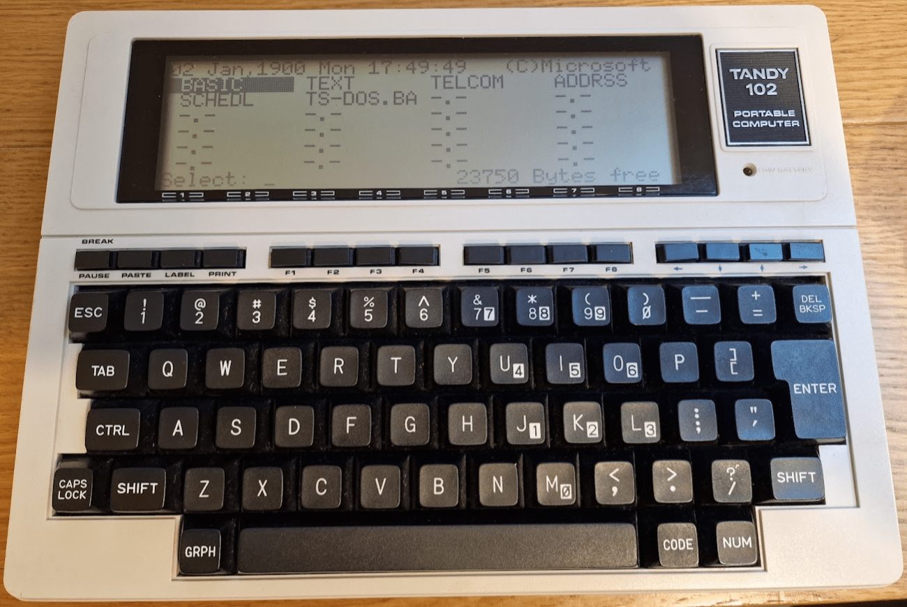
I did however get some hands on with one particular legendary computer back in the 90s which was a Tandy 102. A lot has been written elsewhere about this computer and its place in history so I won’t talk about that any further here, except to say that it must be one of the candidates for being the first genuinely useful laptop computer ever sold. It had built in ROM applications including a programming language, a serial and parallel port, a built-in modem and an excellent keyboard. To top it off it had long battery life and was light and easily transportable.
I was lent it by a friend, and the idea was that I was going to buy it to use it for my GCSEs but for some reason that never happened and it disappeared from my life again. I did have a lot of fun with it for a spell, and it was the first taste I’d had of actual mobile computing. It even came with a disk drive and dot matrix printer. I’ve always wanted to get my hands on one again, and recently an opportunity arose and I jumped at the chance.
I bought it as fully working, and when it arrived it was in excellent cosmetic condition and with a fresh set of batteries immediately booted up to the familiar applications screen.
However, things immediately went wrong because I could not navigate around the screen using the four arrow keys in the top right. This is a major problem! I could launch BASIC by pressing ‘Enter’, but I found quite a few of the main keys didn’t work and also I was spuriously getting apparently random keypresses appearing on the screen as well as the occasional ‘Menu’ (ie F8) command. With a bit more experimenting I found that many of the F keys along the top row did not work either.
So whilst I had hoped for an easy ride it was obviously going to need some work. Fortunately there is a lot of useful information out there, including detailed technical reference manuals published by Tandy. The first step was to have a close look at the keyswitches for the top row.
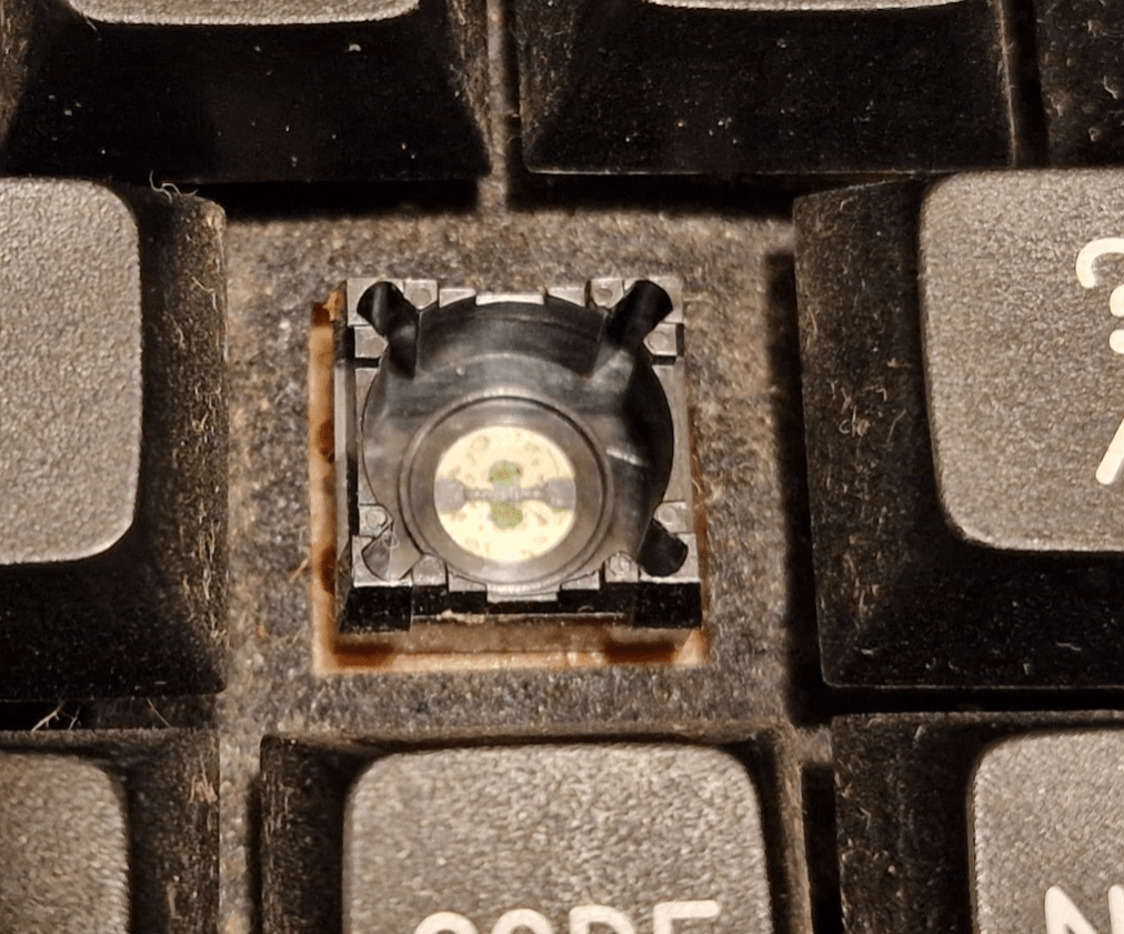
Dismantling the computer is very straightforward and documented in the manual – a few screws underneath and then the top casing lifts off. The screen and keyboard sit on top of the PCB and are connected by flexible cables which can be gently disconnected. Having a close look at the top row of keys was illuminating:
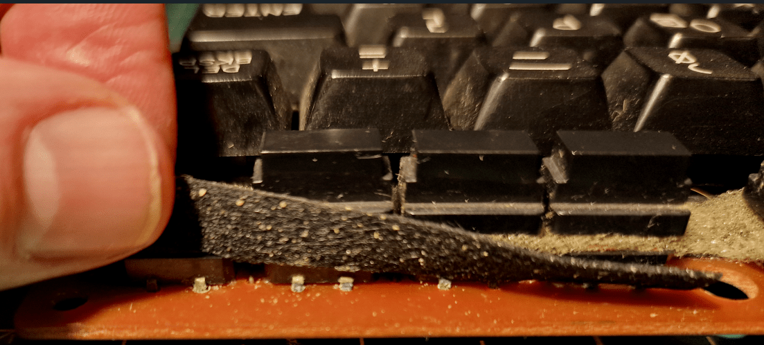
There was clear evidence of corrosion to the pins on almost all of these switches and it seemed highly likely that at best the solder joints were compromised or at worst the whole switch units had rusted. Desoldering one and soaking it in isopropyl alcohol overnight did not help at all so it was clear that I would have to replace them.
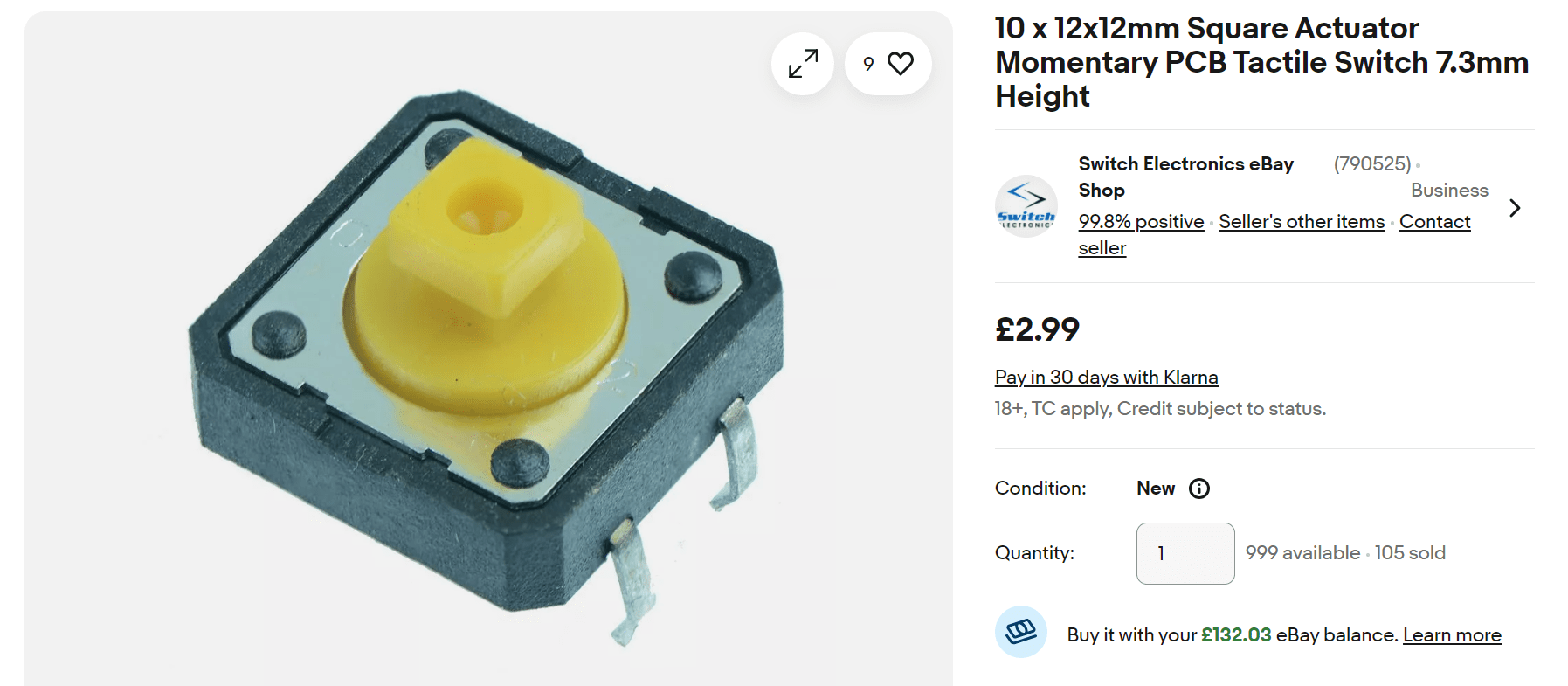
Finding spare parts for things of this age is always a hit and miss affair – some things are readily available whereas others vanished years ago. Keyswitches in particular are often very specific to manufacturers and can be impossible to find. However – the top row of keys are not really keys but more ‘buttons’ and I was very pleased to find that you can still buy identical replacements brand new:
So I was able to desolder the faulty ones and replace them with the new ones, which fitted perfectly and were compatible with the switch tops. On reassembly I was pleased to find that everything worked properly and the cursor could move around freely.

The next thing to do was look at the main keyboard. After some testing it appeared that most keys worked but a few didn’t. I tried hammering on them a few times to see if I could free them up but nothing happened. So after a bit of reading around, I decided to remove the keytops and see if I could do anything. I was able to pull the keytops off and I could see the contacts were corroded:
So after a good scrubbing with some isopropyl alcohol the green rusty substance came off and the contacts were clean and shiny. Once cleaned up and put back together again, they worked fine – so now the keyboard was fully functional again.
The final issue to tackle was the random spurious keypresses. I was getting ‘Enter’ pressed repeatedly, as well some other groups of letters appearing. The excellent ‘Technical Reference Manual’ (why don’t they write these any more) showed that the letters were arising from the same part of the keyboard membrane. There wasn’t anything really obviously wrong but there were some crusty looking joints here and there. I also noticed the problem was worse when the PCB was under pressure (no problem if the casing was off, for example). So I blindly reflowed the solder on a few of these and around the problematic area. This solved the problem, and so I now had a fully working keyboard.
So a good start… but more is to come!