The Sennheiser freePORT radio microphone was a very popular vocal mic, being inexpensive and good quality. It is very much at the budget end of the Sennheiser range and doesn’t have all the fancy features of the more expensive models but still does a solid job.
We have a couple of these at our church which we use for portable use and they get quite a lot of abuse. One of them recently broke so I had a look at it, always being keen to repair rather than replace. The handset had got bashed and there was no audio coming through.
One difficulty with these mics is that it’s not obvious how to get into them. The best place to start it by unscrewing the top of the handset to expose the capsule:
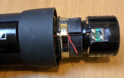
The problem here is pretty obvious, in that one of (very thin) wires which runs from the capsule into the body of the mic has broken off. So a repair should be a simple matter of resoldering it, although there is no slack available here so the whole wire needs to be replaced.
The next thing to do is to remove a screw in the battery compartment, and the collar at the top which fits on to the pop shield:
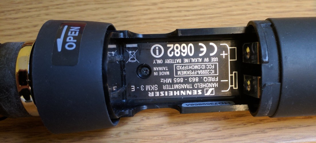
Then you have to remove the shiny black plastic piece which says ‘Sennheiser Freeport’ and covers the electronics. This is much easier if you remove the collar as well:
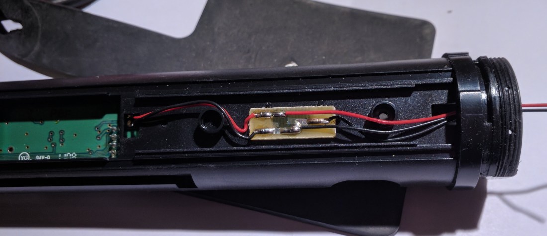
I ended up replacing both of the wires on the right hand side of the picture by desoldering them from the board and replacing them with new. The wires are very fine, and I used two cores from a burglar alarm cable which were the thinnest thing I could find. You have to thread them through the collar to get to the capsule. The black wire goes to the pad marked with a blue dot on the capsule. Once done it’s a fairly simple matter of putting it all back together again.
The other problem I have had with these mics is that the power connector on the receiver tends to get worn out. This is also dead easy to replace. So with relatively little effort you can keep this working in spite of some quite rough handling.

Hi there. I have the same issue with this microphone set. I had to replace all 3 wires in my unit as someone tried to pull it apart when it would not work and broke all the wires. My unit is still not working so I may have soldered the wires incorrectly. Is there any chance you are able to post more pictures for reference? I would greatly appreciate it. Cheers.
Sure I will do so. I don’t have it in hand at the moment but I’ll get it in and take some more. Presumably it powers on ok?
Yes. Powers on fine. I may have accidentally reversed the cables when I soldered replacements in. I will double check. After having a better look at the pictures you have provided, I can see the polarity they should be in. If that is correct I will have to assume the microphone itself is no longer functional. Cheers for the reply.
Regards,
Mark
We have great help from it’s.
That’s great! Glad you found it helpful
What do I have to solder the third wire to?
There are only two wires on the one I have – black and red. Are you sure it’s the same unit? The third wire might possibly be a ground, but usually for mic capsules there are only two wires
Hy, I need Your help. My Freeport Vocal system is still working, but the outcoming sound is weak, I compared with beyerdinamic TG35 …and the lower freq range is “missing” @ the Sennheiser… with eq isn’t good. Has anyone this prblem? electrical drawing of the reveiver?
Hello can you send more pictures? There is three wires in the picutre, one must be an additional ground? Where does the red wire solder on?
Sorry I don’t have this any more so can’t take any more pictures. I’d not noticed the third wire and I can’t remember exactly now but I think the third wire disappears into the body of the mic somewhere and doesn’t connect to the capsule. The black wire goes to the pad with the dot on it, and the red wire goes to the other pad. I don’t imagine that it would make much difference if you wired it the other way round though.
I actually figured it out. I think the extra black is just a 2x ground. I soldered it to the ring holding the wires in place. Thanks so much for your reply!!
Great, really glad you got it sorted
le troisième fil sur la bague!!!
Thanks for the very helpful article!
A few other bits that might help others:
1) There are two screws in the battery area, one shown in the photo, and another hidden between the two metal battery connectors.
2) You can more easily remove the shiny plastic cover by removing the plastic battery compartment locking ring. Just gently force over-rotate the plastic locking ring in the “Open >” direction and it will pop an extra 20-30 degrees of rotation, then slide vertically up and off the microphone. Then you can easily remove the shiny plastic cover piece after both screws in the battery area have been removed.
3) The third ground wire that connects to the metal ring is for grounding the capsule cover.
4) The wires on the capsule are BLACK (left, ground) and RED (right, audio). The ground (left) is marked with the blue ink mark. I also used a red sharpie to mark my audio (right) solder point too, for future reference.
5) The little brown PCB is just a cross connector for convenience. If necessary, you could optionally bypass it altogether, as long as you run a black ground wire to BOTH the metal capsule cover grounding ring, and also to the BLACK/left connector on the capsule.
6) If the wires become unsoldered from the internal green PCB, first remove the little external antenna, then you need to remove 3 screws from the top PCB board, then gently lift up the top board to disconnect it from the bottom PCB board (there is a 10-pin male/female quick connector block between the two boards). The bottom PCB board has two more screws holding it in place. When you remove the bottom PCB and flip it over, there are two connectors labeled “AUD” which is where the RED wire connects, and “GND” which is where the black wire connects.
Cheers!
Ótimo, está sendo de grande ajuda.
Mas estou confuso.
Pesquisando em vídeos sobre cápsulas, vi muitas pessoas informando que como regra os lados que estão marcados com tinta na cápsula, indica o positivo .
E que os fios vermelhos são também positivos.
Assim Eu fiz as soldas.
Fio vermelho no lado ontem tem a marcação com tinta azul e fio preto do outro lado
O preto menor que sai do meio da placa soldei no anel que prende os fios, quase que intuitivamente.
Ao terminar procurei informação na internet e feliz por encontrar essas informações tão valiosas que vocês postaram aqui.
Só que pelo que entendo do as soldas dos fios invertidos
Então, com medo, não testei o microfone
Tive medo de danificar
Se alguém poder me ajudar ficarei eternamente grato
Felicidade a todos
Estou feliz por ter ajudado e desculpe pelo atraso
Não acho que realmente importe muito para onde vão os fios. Então, acho que você pode tentar, não acho que vá causar grandes danos se for ao contrário, mas pode não parecer muito bom.
where can i purchase this mike piece
Even a tiny matter like connecting a mic become a serious issue when there are more wires than there should be. your post really helped me. and also one commenter did very good job explaining all the details. thank you both!!
Excellent – glad it was helpful! It’s always good to hear about success stories.