Whilst I am interested in old tech and computers of all types, I’ve come to realise lately that my favourite brand from the 80s is Amstrad. Not perhaps everyone’s choice, but I was really into Amstrad at the time (owning a PCW 9512 which I would still love to replace). I also used various Amstrad PCs which were something of a phenomenon at the time for their low price. Although I never actually owned any other Amstrad products I followed them eagerly and well remember looking at them in Dixons etc on the High Street. They had a reputation for making packaging up previously expensive or complicated things (eg hifis) and making them cheap and easy to use. Whilst at the time people grumbled about the quality, looking back it now I think that their stuff was actually pretty well designed and well made, and the savings were often made by clever design decisions.
One of the more interesting Amstrad products of this era is the company’s first take on a portable computer – the Amstrad PPC. Laptop / notebook / portable computers in the mid to late 1980s were expensive and exotic things costing thousands of pounds, and the idea of portable PC computing was completely out of reach for most. The PPC followed the usual Amstrad philosophy and delivered a portable computer at substantially reduced price.

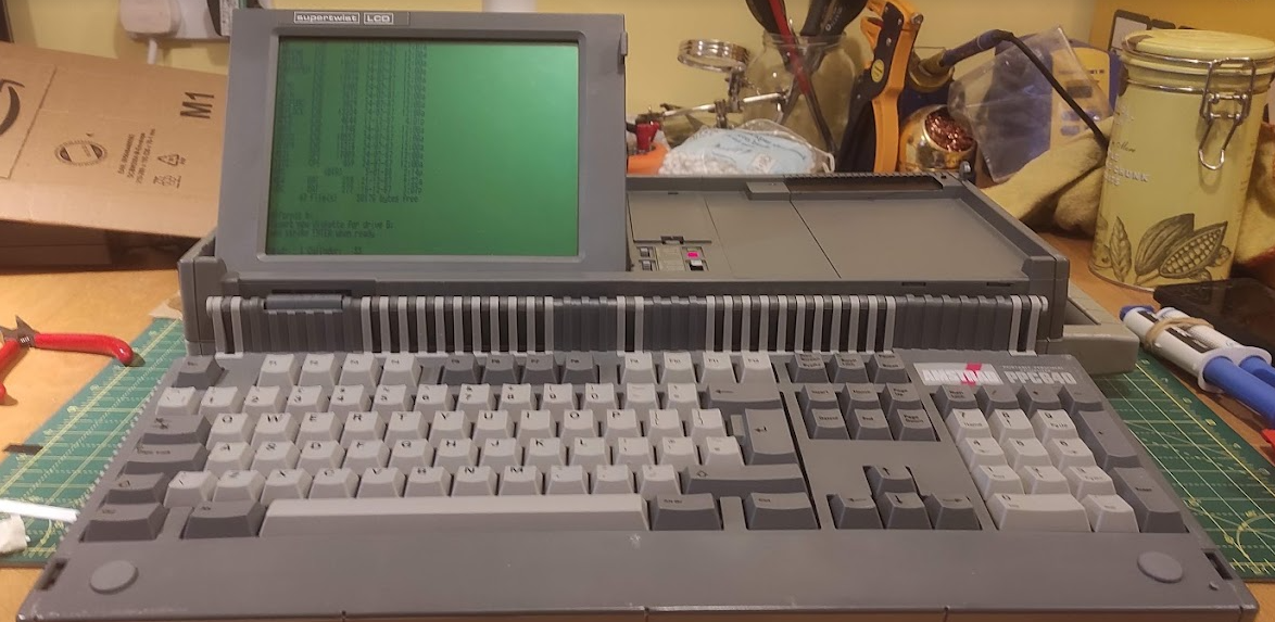
I’ve recently picked one of these up, which is the top of the range PPC640D. The design is really interesting, with a small folding LCD screen, and then a full sized desktop style keyboard which folds over the whole of the rest of the machine. There are two 720k 3.5″ floppy drives on the right hand side, and an internal 2400 baud modem – which was a really impressive addition at the time. The overall package feels surprisingly solid and sturdy.
I bought this without any idea if it worked or not and there have been a few issues. The first concerning getting the machine to start up properly. It came without a power supply, but fortunately (and unlike many portable computers) runs off a standard 12V power supply with a barrel connector (centre positive). You do need a fairly beefy one because of the current requirements. You can also – uniquely I think for a portable PC – run it off standard ‘C’ batteries (10 of them!) although I can’t imagine you’d get much running time.
The power switch (just to the right of the screen) is also a bit odd in that it switches between two ‘on’ states – either ‘battery on’ or ‘external on’. With an external power supply connected I was pleased to see the lights come on and ‘Please Wait’ on the screen. However, after a few seconds there were three beeps and just a flashing cursor. The disk drives ran for a few seconds, but beyond that no response.
There isn’t a huge amount out there written about these machines but I did find this reference to a similar issue. It’s all about a small bank of DIP switches which are hidden away on the side of the machine. The relatively basic nature of the hardware means that the display is not auto-detected in any way and the switches are used to set the display options. If you get it wrong then there is nothing on the screen. There is a useful guide to the DIP switches here. When I got it, all the switches were down ie on, which led to a fault condition in which the internal display was set to a CGA (ie colour) mode but the screen type was set to MDA (ie monochrome). The solution was to either set the screen mode to MDA (switch 2 off) or the screen type to CGA (switch 4 off for 40 columns or switch 5 off for 80 columns). I opted for the latter, and the switches now look like this:

I can’t really work out why they were ever set to all on, except perhaps someone well meaning thinking it looked neater!
The second issue was about the casing itself. Although it felt sturdy enough I could hear bits of plastic rattling around inside. More significantly, there was clearly something wrong with screen hinge, and although it did work it was not very stable and you could see one of the pins on one side was loose.
Getting inside was pretty easy – 6 large screws on the base, with two of them inside the battery compartment. When I got it open I was surprised to find there was a lot more damage than I expected, with several of the screw posts broken off, and various other bits of trim rattling around:
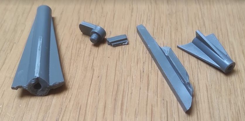
Fortunately, the breaks were pretty clean and it was easy to see where the broken pieces went back, so it was just a question of mixing up plenty of epoxy resin and sticking the various bits back where they came from.
Getting screen out was a bit more tricky, and requires removing one of the motherboards, the modem and several connectors:
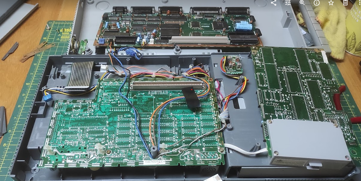
This picture shows where you need to get to. The board at the top of the picture usually sits on top of the other one, with a large connector block as well as a few power cables. The modem is a separate board on the right hand side (with the grey box).
Of particular note are the three ribbon cables top left, two of which are the keyboard and the other the screen. These push in to connectors on the top board:
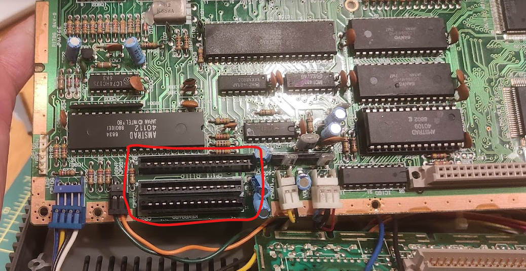
First of all there are a few screws (indicated by arrows) to remove. There are so many different connectors it is tricky to get everything out, but the simplest thing to do is unplug the blue and white connector blocks first, then ease the board upwards and then it should be possible to flip it over so that you reach the ribbon cables, which just pull out. You do need to very careful with these as they are rather fragile.
Having done this, the screen can then be removed. It’s held in place by plastic pegs which locate in holes on the chassis, and with a bit of careful wiggling around it will come out. The problem was immediately apparent:
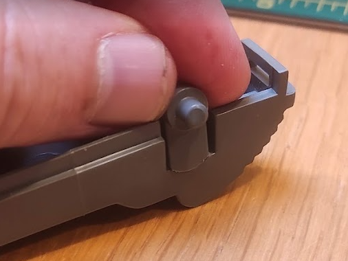
One of the plastic pegs had snapped off. This proved tricky to resolve – the peg is designed to move slightly in and out and is moulded to be flexible, but trying to fix it in place spoils this. I didn’t take enough pictures, but in the end I glued a thin piece of plastic inside the screen behind the peg, and then glued the peg to that to give it more support. Others have suggested drilling a small hole in the peg and using a metal pin for support, or else even more drastic solutions.
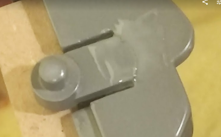
My approach didn’t quite work out as planned. Not all of the glue stuck properly, and the peg is still a bit floppy. However, it’s definitely better than it was before and the screen stays in place. I could have another go at it but it’s good enough for what I want it to do.
Having put everything back together again, it only remains to get it started. The machine did come with a pile of disks including one of the original Amstrad ones. This didn’t work, but with the help of a Greaseweazle (another article for another day) I was able to write a new image out to it:
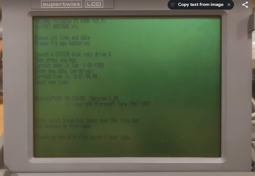
Success! It boots up nicely to DOS 3.3. There’s quite a lot of interesting things to explore with this now, including testing the internal modem. However for now I’m happy to have it restored to working order again, and I’m debating taking it out somewhere and trying to do some real work on it. Would draw a striking contrast with the usual selection of Macbooks seen in my local coffee shop!
