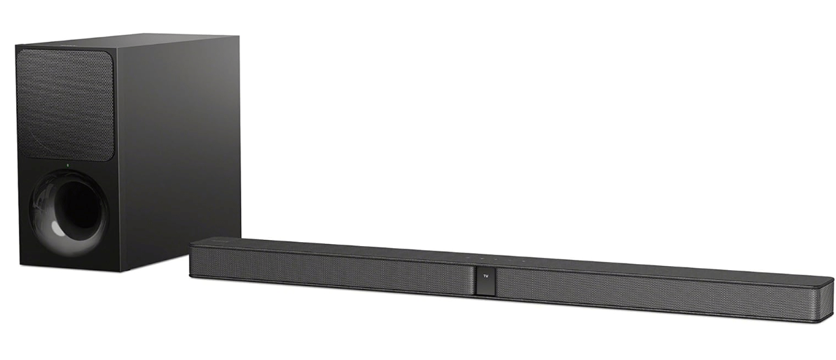
At the most recent Repair Cafe a friend asked me about a wireless subwoofer for a soundbar which was not working. It was completely dead with no signs of life.
On closer inspection it proved to be a Sony HT-CT290 soundbar (which was working fine) and a separate SA-WCT290 subwoofer.
It’s common especially when things are completely dead that the fault lies in the power supply, which often relatively easy to repair (bad capacitors or similar issues). So I was hoping to find something similar here. A bit of quick searching around revealed this to be a relatively common fault with a voltage regulator which steps the 18V down to 3.3V for the control circuits.
Getting access to the circuit board is fairly easy, just a question of removing all the screws on the back of the unit. The PCB is fixed to the rear panel, and there are two cable connectors to unplug from the main board (one for the LEDs and one for the speaker). Then it’s quite easy to see what’ going on:
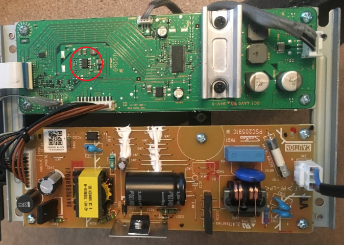
The large brown PCB is the main power supply board, and the green one has the rest of the supporting circuits. This board steps down the 240V AC to 18V DC. With the board powered up it was possible to check the voltages at various points as outlined in the service manual. The 18V seemed to be getting through OK which ruled out any problem with the brown board.
The chip circled in red on the green board is a TPS54334 step down voltage converter (sometimes called a DC:DC or buck converter) which is a general purpose device but in this case is set up to reduce the 18V input to 3.3V output for the low voltage circuits. The service manual suggests measuring the voltage at one of the connectors, but for some reason neglects to mention the two large ‘test pads’ just next to it (on the left of the red circle in the picture above). The service manual states that if the voltage is anything other than 3.3V to replace the board.
On the one I had, the voltage was 2.90V – so not much lower, but definitely not 3.3V and actually more than 10% out of tolerance. Other people have reported the output as being 0V, but given that the reading was clearly wrong it seemed logical to start there. This chip is a surface mount device and unfortunately I don’t (yet) have the kit or the skills to rework this. There’s a great video where someone does just this:
So I was contemplating doing this, but then I came across an interesting thread on iFixit which describes a similar problem and solution. However, further down the thread comes the genius idea to ignore the SMD work completely and replace the part with a separate buck converter board (which are widely available very cheaply) with the input 18V taken from the power connector (first three pins), and the output 3.3V fed into the test points described above. Rummaging around in my junk box I was delighted to find just such a module left over from an old project, in this particular case based on an MP1584 chip:

These converters all work in the same way, in that you feed an input voltage in one side and then adjust the small screw to set the output voltage. This particular one has a tiny and very sensitive screw, and after connecting it up to an 18V source it took quite a lot of very fine adjustment to get it to output exactly 3.30V.
It was then simply a matter of wiring the input to the 18V supply pin on the power connector (I used pin 1) and the output to the test pads (the positive one helpfully labelled ‘+’). The ground is all commoned together so I only wired in one negative lead. I stuck the module to a spare piece of board with a ‘sticky fixer‘ and secured the leads with tape. I also took the precaution of snipping off all the leads of the old IC although I didn’t actually remove it. This is hard to do as it has a big blob of solder on the back holding it to the board for heat dissipation.

With the board powered up, all the voltages looked good so it was a matter of putting everything back together and looking for signs of life:

I was very pleased to see a green light appear – and everything appeared to be working properly. Not having the actual bar I could not test it myself, but the owner later reported that it was back to full working order which was very pleasing.
Once again, a relatively complex piece of electronics was defeated by a simple power supply problem and the generous provision of test points made it very easy to replace. SMD devices are a pain for a casual hobbyist like myself, although it is now getting cheaper and easier to obtain the kit to work them it’s still a whole lot more difficult. Overall though, a great result and this does appear to be a very common problem with this model. There are also reports of the same thing happening in the soundbar itself.
Let me know in the comments how you get on if you attempt something similar

Had the same problem with this type of Sony subwoofer: no 3.3 VDC. Luckily, I read your article on the internet and followed your instructions. After connecting an external MP1584 to the board, the problem was solved. Thank you for sharing this practical solution.
Michael
Great stuff – thanks for letting me know.
Thank you for the description!
Great Work and Great help for me!
Great! Thanks for letting me know
Hi How can I get the board MP1584 not only the chip.
Thank
I think these usually come as a module with the board and chip together. It may be possible to buy the chip separately but if you look on ebay or Aliexpress you should find what you need