Repairing an Epson HX-20 – Tape Drive & Printer

With the new battery in place it was time to test the main peripherals – being the cassette and the printer. The cassette drive is actually a plug in module – it could be replaced with a ROM cartridge, and as originally shipped with a simple blanking plate. The quality of the engineering is superb – it feels very solidly made and slots into place with a very positive action. I have a cassette supplied which contains the original logging program for the data logger complete with instructions.

As described above, the tape transport is entirely under computer control including winding, and there is even a digital tape counter accessible from BASIC. The ‘WIND’ command rewinds the tape, and I was pleased to find that sure enough it rewound to the beginning. The ‘LOAD’ command (as expected!) searches the tape for something to load so I typed ‘LOAD’… and nothing happened. No sign of life from the drive at all, and the computer reported a ‘IO error’.

It is very common for old cassette machines to have problems with their drivebelts as the rubber stiffens and perishes over time. However the belt was likely intact to some extent because the winding mechanism seemed to work. It clearly did need the drive stripping down and servicing, and this proved to be quite a task.

Looking round the ‘net it is possible to find some information on how to do this. Given the small scale it is unsurprisingly quite a fiddly job. I’ll make a list of useful HX-20 sites but I’d start with this excellent resource from Martin Hepperle, and specifically the ‘Tips and Tricks for the HX-20‘ PDF:

https://www.mh-aerotools.de/hp/hx-20/index.htm

There’s loads of useful stuff in here, including some advice on replacing the drive belt. There is also a huge stack of other manuals – including a massively detailed technical reference manual – here:

http://www.vintagecomputer.net/fjkraan/comp/hx20/doc/

The technical manual gives a very nice exploded diagram of the tape drive, and in conjunction with Martin’s guide tells you everything you need to know. However it is extremely fiddly. The drive itself is a modular unit which slides out (and I understand it originally shipped as an optional extra). There are a few screws to remove the outer shell, and then several more which hold the PCB to the back of the drive mechanism. Some of them have brass standoffs, and all of them are really small so great care is needed not to lose any.

One of the hardest things to do is separate the mechanism from the top shell – it’s not clear how to do it, and takes a lot of wiggling around with the door open to do it. The technical manual talks about removing the front of the tape door but I couldn’t see how to do it and after a lot of fiddling around it eventually came off. So I can’t really offer any advice other than to persevere!

One thing I did learn – do not under any circumstances remove the screw which forms part of the door release latch assembly. I did this thinking it would make things easier, and in doing so the tiny spring which reset the eject switch popped out. I spent a very long time trying to get it back in again… which was incredibly difficult to do. After countless unsuccessful attempts I was eventually able to do it although the spring ended up rather buckled in the attempt.

Once you have the mechanism out you need to unsolder a few wires from the motor, remove the tachometer cap and then finally you can unfold the mechanism and reveal the belt. I had got so absorbed in the process that I didn’t take many photos unfortunately but there are details in the guide linked to above.

To get the belt out, you have to remove another metal bar which sits across the mechanism. The one on mine was intact but had clearly hardened up and was very slack and clearly would not do a good job. However it did not explain why the drive was not working at all, as even a missing belt should still allow the mechanism and motor to start. The belt itself is 50mm in diameter (so about 160mm circumference) with a square cross section. I have a bag of belts of varying sizes so tried a few until I found one which fitted. They do need to be thin enough to pass underneath the tachometer cap so a bit of experimentation may be needed. The cross section should be anything between 0.8mm and 1.2mm square – mine was 1mm.

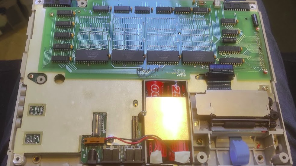
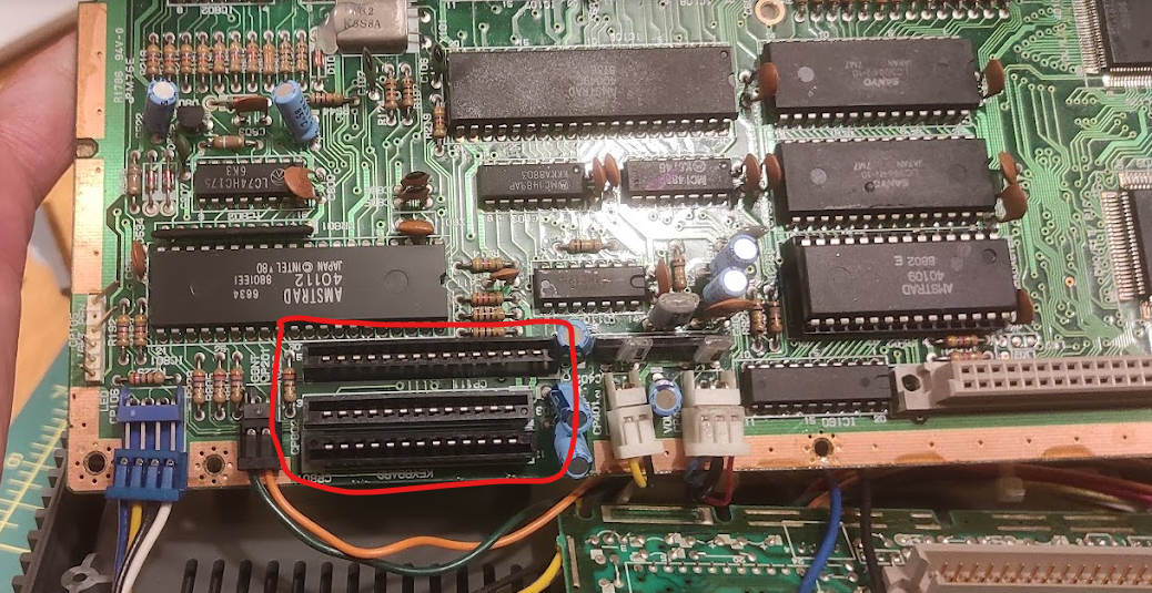
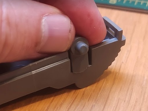
I then roughly reassembled the module and slotted it back in to see what else was wrong. It was clearly obvious that the real problem was that the tape head was not engaging, and so the computer was behaving as if no tape were loaded. The mechanism is circled on this picture, although here it is in the engaged position.

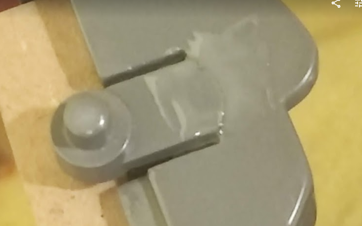
This mechanism is driven by a separate motor with a worm drive which moves the head in an out of position in a continuous loop. A sensor detects when it is in place which stops the motor. On initial inspection I could not see anything wrong. With long nose pliers I could turn the motor shaft and the mechanism worked smoothly. So the problem either lay with the motor itself or the logic driving it. To test this further I desoldered the wires from the motor (circled on the picture below) and used an external battery pack to see if I could get any life out it:

Initially it appeared completely dead, which was not good news. However, after a bit of fiddling around and without seemingly having done anything, it suddenly burst into life! I spent quite a few minutes watching the motor run smoothly and engaging and disengaging… quite hypnotic. I’m still not quite sure what made the difference, but I think the most likely thing is that the motor had seized through lack of use and a combination of moving the shaft manually and the external power source was enough to kick it into life.

It was then simply a matter of further testing. I reassembled the unit without the case, took a deep breath and…

Success!

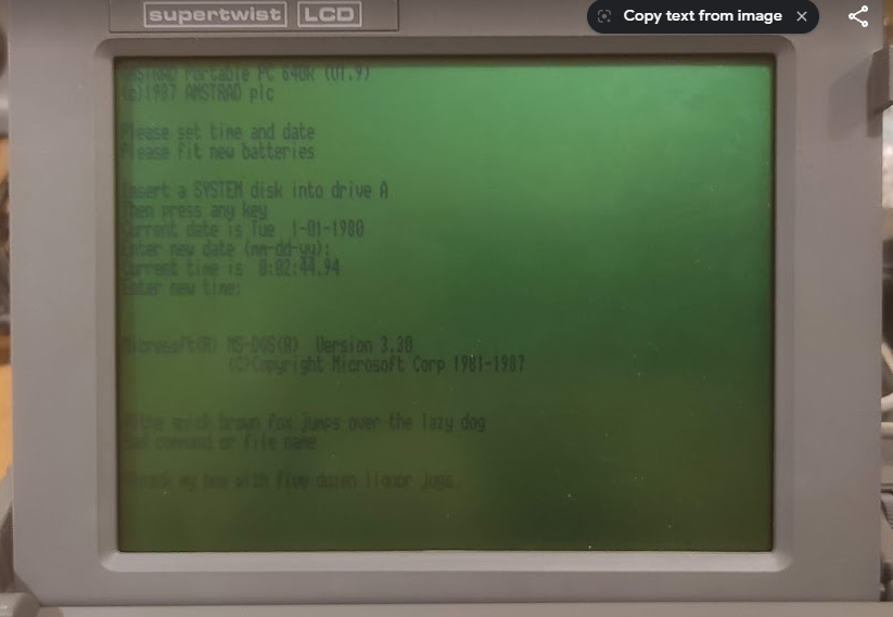
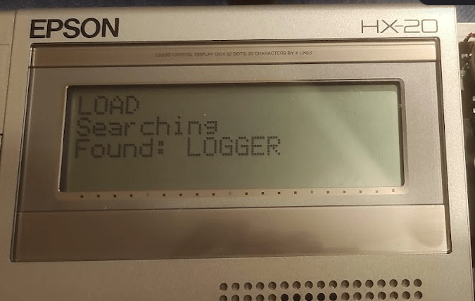
It was then a matter of reassembling properly and testing with an actual tape. My unit was was used with a data logger and came with the logging program on tape. It’s not been touched for many years, but I put the tape in typed the ‘LOAD’ command and to my great satisfaction it found and loaded the program:

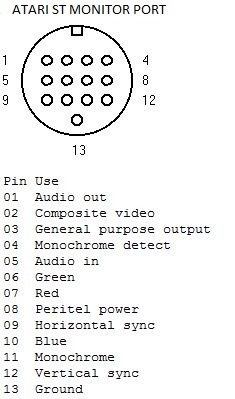
The final piece of the puzzle was the printer. It was clearly working although the ribbon in it had completely disintegrated. Amazingly you can still buy brand new replacements as a similar mechanism is still used in some cash registers:

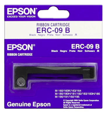
You can easily find these – either originals or cheap knock-offs – online very cheaply. On installing it, I was pleased to find that the printer did work but I had a lot of trouble with it apparently jamming. The paper would advance very slowly with constant beeping from the computer. This turned out to be simply due to the plastic gears binding due to a lack of lubrication, and a quick spray with a silicone lubricant (designed for plumbing, but great also for plastic gearing) left everything working smoothly. You can ‘screen dump’ direct to the printer or output to it in BASIC.

The quality is surprisingly good, and I have a box full of original branded Epson paper rolls although these also are widely available.

So after quite an interesting journey I now have a fully working HX-20. There is plenty of other stuff to explore – although the HX-20 scene is quite limited, it is still possible to find software from various sources which can be loaded through an external tape port. I would also really like to see what the data logger can do, will have to think up a suitable retro project for it. Also need to clean up the case a bit. It remains one of a very small group of computers which have printer, display and storage in a single unit. In fact the only other one I can think of is the much later Canon NoteJet / BubbleNote series of laptops

This whole thing has given me a taste for these quirky early portable computers, and I know I would have absolutely loved something like this back in the 80s. Watch this space for more adventures…

Repairing an Epson HX-20 – Battery Pack

The first job then was to see what I’d got and what state it was in. Like many portable computers the HX-20 has an internal battery pack and these are prone to failure and if the cells leak they can make a complete mess of the internals. It’s clear that the previous owner was very far sighted, as the original cells had all been removed. They were in the case though and showed clear evidence of leakage – I shudder to think what would have happened if they had been left inside:

An oddity of the HX-20 is that whilst it has an external power socket (and my examples comes with the original Epson branded power supply) this is actually for a battery charger. So whilst it will power up if connected, it doesn’t work properly (neither the printer nor the tape drive function) and the voltages are all over the place. If you use it like this for any period of time it’s not going to do it any good at all and would probably cause some damage eventually. The battery forms a vital part of the power system and therefore a new pack is needed for everything to work.

The original pack is made up of ‘sub-C’ cells, which I’d not come across before but which are commonly used in rechargable battery packs. The original pack had a capacity of about 1000mAh. It is fortunately very easy now to get hold of cells of all sizes from various online retailers.

The battery connects to a two pin header on the main board, and fortunately the original connector was still intact. The original pack was a sealed unit, but I made a replacement by buying tagged cells. The positive and negative wires were soldered to tags on two of the cells, and the other two arranged in series to make a complete battery. There was just enough room for everything to fit snugly:

The new pack has a much larger capacity and I imagine it would run for a very long time, even with the printer and the cassette in use. It’s definitely more than enough for my needs. The charging circuit is also very rudimentary, and the manual suggests various formulae for calculating the charging time. There is no automatic shutoff or anything clever like that, so you do need to be careful about how long you charge it for.

So now we have power, and the computer boots up fine and is perfectly usable. So the next thing was to look at the tape drive. After the battery pack, this should be easy…

Repairing an Epson HX-20 – Introduction

I’ve recently got hold of a very interesting retro-tech bundle. I browse the auctions (both traditional and on ebay) from time to time and picked up this bundle. It ticks all the boxes for me – interesting item, with lots of original accessories and manuals, and a bit of a project into the bargain:

If you haven’t recognised it by now, this is an Epson HX-20 which is generally regarded as “the world’s first laptop” and which dates back to around 1980. It is quite a famous machine (although not particularly rare) and there’s a lot of information out there about it. However what’s interesting is that although it clearly was groundbreaking, a few shortcomings (notably the small screen) and the fact that it was probably slightly ahead of its time meant that outside some specialist applications (more later) it didn’t really ultimately succeed as a general purpose computer. The TRS-100 / Tandy 102 ended up as the clear winner in this regard.

I’ve got a lot of time for the Tandy machines and I did actually have one for a period many years ago. However what I really liked about the HX-20 was the clear quality of the design and build and also the fact that it has all the key aspects of a 1980s computer – screen, keyboard, storage and printer – in one very small and integrated package. There are also some very neat touches, such as the micro-cassette drive which is controlled entirely by the CPU.

The one I have came complete with the original carrying case, manuals, two boxes of printer rolls and various other documentation. It also came with a data logger also in its case with all the original documents, even the original invoice. I’ve got some more work to do to research it’s origin but it looks like it was used for something to do with testing and monitoring industrial heating systems. I’ll cover this aspect in another post. I’ll also continue the story in a separate post to keep things manageable. So without further ado…

New v6 Premier Elite Firmware

Texecom have just released v6 of the firmware for the Premier Elite panels:

https://www.texe.com/uk/news/#new-premier-elite-v6-and-smartcom-v4-firmware

The main benefit here is a new ‘Monitor Mode’ which is meant to make it easier to set up SmartCom units, apps, Texecom Cloud etc. So definitely worth investigating further as I do have a SmartCom. I’ve not been able to explore Texecom Cloud really because I’m not a professional installer although if you have multiple systems to manage it sounds like an interesting option.

So far as I can see without Texecom Cloud the only way to upgrade the firmware is with the good old fashioned programmer so I’ll have a look at this in the next few days.

I am impressed by the longevity of these panels and that they are still being fully supported an updated. I think mine was on v2 when I bought it. It will be interesting to see how long this continues – I would like to see an easier way of upgrading the panels but it may be that this will remain a ‘premium’ feature.

Repairing an AEG Favorit ComfortLift FSK63800P Dishwasher

When my kitchen was replaced a few years ago, part of the deal was a new dishwasher. As I have written on here before I am keen on high quality appliances and unfortunately because of the deal I didn’t get my preferred choice. Normally I’d go for Miele or Siemens, but to my dismay I ended up being given an AEG. This is one of those brands which used to be good but has ended up be absorbed by a much bigger group and in doing so has lost its way. The same thing seems to have happened to other once-great brands such as Zanussi and Hoover. Still I was hoping for the best…

The model I have ended up with is a Favorit ComfortLift FSK63800P, rather like the one shown in this video:

Unfortunately, unlike my old Miele dishwasher which worked almost faultlessly for a decade I’ve already had a fair amount of trouble with this and I’m less than impressed. However I have been able so far to remedy most of it which I’ll explain here in case anyone else encounters the same thing.

The first problem I’ve had is with the much-vaunted ‘ComfortLift’. This is a hydraulic mechanism which allows the lower basket to lift up as you pull it out. The idea is that it makes it easier to load. No doubt this is true, but the price you pay is that the mechanism is unreliable and prone to getting stuck. The system is quite an interesting feat of engineering and as you pull the basket out some metal pegs engage in a track on the side of the basket which are attached to the metal ‘swing’ arms. I’ve now had a few occasions where the basket has got stuck half-way or fully up.

This is a major headache, because it means you can’t use the dishwasher at all because you can’t close the door. It happened so so often that I got AEG out to replace the whole mechanism under warranty, but it’s now happened with the new one as well. After a lot of fiddling around it seems that the main reason is that the pegs somehow jump out of their tracks and so the whole thing is misaligned and won’t budge. The solution to this is to pull the ‘arm’ on each side outwards to take the pressure off the pegs, and try to guide them back into the tracks. It’s hard to explain this in words but this approach has saved my bacon several times now. I think the deisgn is fundamentally flawed though and this will happen sooner or later, and on this alone I couldn’t recommend the ‘ComfortLift’ to anyone.

The second problem is related to the ‘ComfortLift’ but presented in a very odd manner. One day and without warning in the middle of a cycle the dishwasher started beeping, and the display showed an i30 error whilst at the same time the pump was running constantly. The only way to stop it was to turn it off at the mains.

https://www.aeg.co.uk/support/support-articles/dishwashing/dishwashers/dishwasher-displays-error-code-i30/

This code indicates that the ‘anti-flood’ device has activated, which basically indicates that the inside of the machine at the bottom is full of water and that in turn means that there is a leak somewhere. I didn’t like the sound of this at all, and was on the point of booking a repair at great expense with AEG when by chance I found this video:

This gave me the confidence to investigate further as it seemed highly likely that I had a similar problem, caused by the internal nuts which secure the ‘ComfortLift’ mechanism working loose and allowing water to leak through and drip down into the undertray. Once again it seems like either bad design or poor quality control that such a thing could even happen… no use of lock nuts or any other measures like that.

I don’t like working on integrated appliances because they are such a pain to work on, and getting it out required unscrewing various brackets and fixings. Then when it was out, there are large metal panels on each side which needed removing. This is shown in the video, but in essence what you have to do is remove the kick plate from the front and then a few other screws, and there are a series of large plastic clips at the back which need pressing in which release the side panels. Be very careful when doing this – the metal is thin and razor sharp and I ended up with a nasty cut on my finger. The trick is to us a stout screwdriver or a pair of pliers to push the clips in, and when you have done this the side panels can be removed and the soundproofing moved out of the way to reveal the mechanism.

The first thing to do was to remove all the floodwater and that was a particularly unpleasant task. I don’t know how long this has been going but the water was filthy and full of bits of old food and grease – ugh. It’s quite difficult to get at as well – best bet is to remove the front kick panel completely and use a syringe or pump to get the worst of it out. I didn’t have it at the time but I’ve since bought a 100ml ‘bladder syringe’ and plastic pipe which would be ideal next time around.

Just as in the video linked above, the problem was immediately apparent:

There are three large nuts on each side which secure the swing arm mechanism to the main body. It’s quite solidly made as it does have to support a lot of weight if it’s full of crockery. All three nuts were extremely loose on both sides, and in several cases had spun a long way up the thread and were well away from the side wall. It was really surprising quite how loose they were and it was quite obvious from all the muck where the water had leaked down into the base. It was a simple matter to tighten them all up again. Ideally I’d have liked to put some sealant on them but I didn’t have any to hand, and I needed to get it all working again. After that it was simply a matter of snapping the side panels back on, putting all the screws back in and reinstalling it. As the flood had been cleared everything worked fine. What I don’t know is whether this will recur, and I may need to revisit this with some sealant to make absolutely sure.

The final (and ongoing) problem I’ve had is with the machine randomly stopping mid-cycle with an i20 error.

https://www.aeg.co.uk/support/support-articles/dishwashing/dishwashers/dishwasher-displays-error-message-i20–e20-c2-f2-and-al6-not-draining/

This error indicates that the machine isn’t draining properly… but the trouble is that it is draining absolutely fine. The sump is empty and there is no excess water anywhere. So it points to a problem with the sensing mechanism rather than anything wrong with the drain. This is done by a fairly simple pressure switch, which is connected to a short pipe which is part of the sump. On reading around a bit, it appears that the pipe often gets clogged up with gunge which can lead the sensor to give false readings and make the machine think it is full when it isn’t. As a short term fix, I’ve found that filling the sump with white vinegar overnight seems to solve the problem for a few weeks or months, although it recurs after that.

I’m not entirely sure but I think the sensor plugs into the ‘155A’ connector on the diagram above (very handily available on the Electrolux spares site, which is also covered on the inside of the sump by a ‘sump screen’. So I think what I need to do is get the screen out somehow and use the syringe mentioned above to give the pipe a good swill out. An alternative I suppose is to dismantle everything again and remove the sensor from the inside and clean it out that way, but that’s a lot more work and I’m keen to avoid it.

So overall it’s good news and bad news – had various issues, but so far been able to fix them myself. However, given it’s still quite new I’ve had a lot more trouble than I would have liked and next time round I’ll make sure I get the brand I actually wanted!

Repairing a ZX Spectrum 48k

My first proper computer was a rubber key ZX Spectrum 48k. This was a very popular choice in the early 1980s and I well remember my Dad bringing it home from Boots one day after it having been on order for a long time. Over the years since I have always hung on to it although following a resurgence of interest in the early 90s I messed around with it a bit which led to me replacing the top with a new keyboard as my original one had become very scratched and the keys stopped working. Also somewhere along the line the motherboard was also changed, so actually there’s not much left of my original machine now.

After digging it out, I was pleased to find it had stayed in pretty good nick. It doesn’t have the original power supply (I remember accidentally melting it when doing some experiments many years ago) but other than that is complete. It started up first time but perhaps predictably the keyboard had failed again.

I remember when this happened to me back in the early 90s, and I had really no idea what had happened or what to do about it. I ended up getting hold of a home-made external keyboard which I found in my school physics lab which worked perfectly, although sadly I no longer have it after a much regretted clearout when I was a teenager and this stuff all seemed so ‘1980s’ and boring.

It’s now very easy to get replacement membranes from eBay and other sellers which are apparently much better quality than the original. Replacing the membrane can be tricky and it depends a bit on how old your Spectrum is and what design was used. The case screws release the keyboard assembly from the top, but the ribbon cables need to be carefully detached from the motherboard by pulling them out.

The actual membrane is underneath the rubber key mat, which is in turn held in place by the metal template which has the key markings on it. On my old Speccy it was held on with double sided sticky tape which was surprisingly difficult to remove and I ended up making a right mess of it with it getting bent out of shape. At some point in the past I swapped out the broken one for a new top casing and on this one there are metal pegs which hold it on which need pulling straight:

Then it’s simply a matter of pulling the old membrane out, threading the tails of the new one through and replacing the rubber mat on the top:

Then it’s simply a matter of putting it all back together again, and as expected everything worked fine. On to the next!

Amstrad PPC640 Restoration

Whilst I am interested in old tech and computers of all types, I’ve come to realise lately that my favourite brand from the 80s is Amstrad. Not perhaps everyone’s choice, but I was really into Amstrad at the time (owning a PCW 9512 which I would still love to replace). I also used various Amstrad PCs which were something of a phenomenon at the time for their low price. Although I never actually owned any other Amstrad products I followed them eagerly and well remember looking at them in Dixons etc on the High Street. They had a reputation for making packaging up previously expensive or complicated things (eg hifis) and making them cheap and easy to use. Whilst at the time people grumbled about the quality, looking back it now I think that their stuff was actually pretty well designed and well made, and the savings were often made by clever design decisions.

One of the more interesting Amstrad products of this era is the company’s first take on a portable computer – the Amstrad PPC. Laptop / notebook / portable computers in the mid to late 1980s were expensive and exotic things costing thousands of pounds, and the idea of portable PC computing was completely out of reach for most. The PPC followed the usual Amstrad philosophy and delivered a portable computer at substantially reduced price.

I’ve recently picked one of these up, which is the top of the range PPC640D. The design is really interesting, with a small folding LCD screen, and then a full sized desktop style keyboard which folds over the whole of the rest of the machine. There are two 720k 3.5″ floppy drives on the right hand side, and an internal 2400 baud modem – which was a really impressive addition at the time. The overall package feels surprisingly solid and sturdy.

I bought this without any idea if it worked or not and there have been a few issues. The first concerning getting the machine to start up properly. It came without a power supply, but fortunately (and unlike many portable computers) runs off a standard 12V power supply with a barrel connector (centre positive). You do need a fairly beefy one because of the current requirements. You can also – uniquely I think for a portable PC – run it off standard ‘C’ batteries (10 of them!) although I can’t imagine you’d get much running time.

The power switch (just to the right of the screen) is also a bit odd in that it switches between two ‘on’ states – either ‘battery on’ or ‘external on’. With an external power supply connected I was pleased to see the lights come on and ‘Please Wait’ on the screen. However, after a few seconds there were three beeps and just a flashing cursor. The disk drives ran for a few seconds, but beyond that no response.

There isn’t a huge amount out there written about these machines but I did find this reference to a similar issue. It’s all about a small bank of DIP switches which are hidden away on the side of the machine. The relatively basic nature of the hardware means that the display is not auto-detected in any way and the switches are used to set the display options. If you get it wrong then there is nothing on the screen. There is a useful guide to the DIP switches here. When I got it, all the switches were down ie on, which led to a fault condition in which the internal display was set to a CGA (ie colour) mode but the screen type was set to MDA (ie monochrome). The solution was to either set the screen mode to MDA (switch 2 off) or the screen type to CGA (switch 4 off for 40 columns or switch 5 off for 80 columns). I opted for the latter, and the switches now look like this:

I can’t really work out why they were ever set to all on, except perhaps someone well meaning thinking it looked neater!

The second issue was about the casing itself. Although it felt sturdy enough I could hear bits of plastic rattling around inside. More significantly, there was clearly something wrong with screen hinge, and although it did work it was not very stable and you could see one of the pins on one side was loose.

Getting inside was pretty easy – 6 large screws on the base, with two of them inside the battery compartment. When I got it open I was surprised to find there was a lot more damage than I expected, with several of the screw posts broken off, and various other bits of trim rattling around:

Fortunately, the breaks were pretty clean and it was easy to see where the broken pieces went back, so it was just a question of mixing up plenty of epoxy resin and sticking the various bits back where they came from.

Getting screen out was a bit more tricky, and requires removing one of the motherboards, the modem and several connectors:

This picture shows where you need to get to. The board at the top of the picture usually sits on top of the other one, with a large connector block as well as a few power cables. The modem is a separate board on the right hand side (with the grey box).

Of particular note are the three ribbon cables top left, two of which are the keyboard and the other the screen. These push in to connectors on the top board:

First of all there are a few screws (indicated by arrows) to remove. There are so many different connectors it is tricky to get everything out, but the simplest thing to do is unplug the blue and white connector blocks first, then ease the board upwards and then it should be possible to flip it over so that you reach the ribbon cables, which just pull out. You do need to very careful with these as they are rather fragile.

Having done this, the screen can then be removed. It’s held in place by plastic pegs which locate in holes on the chassis, and with a bit of careful wiggling around it will come out. The problem was immediately apparent:

One of the plastic pegs had snapped off. This proved tricky to resolve – the peg is designed to move slightly in and out and is moulded to be flexible, but trying to fix it in place spoils this. I didn’t take enough pictures, but in the end I glued a thin piece of plastic inside the screen behind the peg, and then glued the peg to that to give it more support. Others have suggested drilling a small hole in the peg and using a metal pin for support, or else even more drastic solutions.

My approach didn’t quite work out as planned. Not all of the glue stuck properly, and the peg is still a bit floppy. However, it’s definitely better than it was before and the screen stays in place. I could have another go at it but it’s good enough for what I want it to do.

Having put everything back together again, it only remains to get it started. The machine did come with a pile of disks including one of the original Amstrad ones. This didn’t work, but with the help of a Greaseweazle (another article for another day) I was able to write a new image out to it:

Success! It boots up nicely to DOS 3.3. There’s quite a lot of interesting things to explore with this now, including testing the internal modem. However for now I’m happy to have it restored to working order again, and I’m debating taking it out somewhere and trying to do some real work on it. Would draw a striking contrast with the usual selection of Macbooks seen in my local coffee shop!

Upgrading a Commodore 64 power supply

One of the first things I bought when I came back to retro computing was a Commodore 64. I’d never had one of these before, having been firmly in the Spectrum camp when I was growing up. For some reason I’d never really had the curiosity to explore this before but I decided the time was right and bought a decent bundle off eBay, which came with a handsome bundle of games which were fun to explore. It was also interesting experiencing tape loading complete with music which didn’t happen on a Spectrum.

One thing I quickly discovered on reading around was that the original power supply was something of an accident waiting to happen, with some quite sensational articles with dire warnings of impending doom. Unlike a lot of early computers it is a reasonably complex power supply with a 9V AC and a 5V DC rail which feeds a DIN plug, and so it’s not absolutely straightforward to replace.

The original design of these is extremely odd (it seems to me) in that the they are fairly simple devices with a transformer and voltage regulator, but then the whole lot is encased in epoxy resin making it a heavy and completely solid block. I really can’t imagine why they did this, other than perhaps to make absolutely sure that no-one actually tried to service it. I’ve not seen any other computer manufacturer of the day do anything like this. The problem referred to above is due to a breakdown of the DC voltage regulator, which is buried in the epoxy resulting in a significant over-voltage and generally a destruction of the C64 itself. The epoxy is also poor at radiating heat which I’m sure doesn’t help the situation

There are various opinions out there on what to do about this – most people recommend avoiding the stock PSU, although I tested the voltages on mine and it was fine. There are quite a number of third party units which are very nice, but rather expensive for what they are:

After a lot of debate, I took the view that the only issue with the stock PSU was the regulator, and after finding a few other examples of people who had modified it I thought I would do the same. There are various different types of these, but mine is the so-called ‘wedge’. Others are just big rectangular bricks, but all of them have the same epoxy construction.

The first thing to do is get into it – easier said than done. The plastic base is glued on, and part of it is buried in the epoxy itself. So it does take a lot of pushing and prying (and some cutting with a sharp knife) but eventually it comes off. All you can see is what is below – most of the wiring is buried in the epoxy but there are taps straight of the transformer for the AC supply, and then via a regulator (circled in red) for the 5V DC.

So there are two jobs to do – the first is disconnect the existing regulator, and the second is to provide some kind of modern alternative. The first is a fairly simple matter of desoldering the pads and cutting off and removing the regulator legs. You could probably manage without this but I really wanted to make sure there was no danger of issues down the line.

There are various modules out there for regulating / rectifying voltages (Buck converters etc) but the guide I linked to above suggested using a ‘UBEC’ (Universal Battery Eliminator Circuit). This is something used in remote control vehicles for getting high voltage battery pack outputs converted down into the lower voltages needed. So it’s ideal for my needs, which is to convert the 9V AC from the transformed into the 5V that I need.

These are cheap and easy to find on eBay and all the other usual sources:

These are not particularly sophisticated devices, and there is apparently a fair bit of electrical noise on the output but these older computers are not sensitive enough to be troubled by it. You do have to configure the UBEC with jumpers to get the 5V you need. It’s also small enough to fit neatly inside. You need to connect the input to the UBEC from the main smoothing capacitor, and the output to the output pin from the voltage regulator (the right hand one on the the photo below). The negative output can simply be left unconnected.

If you’ve done it right, then you should be able to measure about 5V coming out and off to the C64. It’s then just a matter of fitting everything back together again.

Overall it’s a fairly easy job and I am now confident that I can use the power supply without issue. A nice spinoff is that it runs much cooler and still looks authentic. It’s been running happily for long periods with no problems at all.

Atari ST monitor cable – DIY / NOS

Since last posting things have moved on considerably and I have picked up quite a lot of new and interesting items. I’m going to go into these in more detail as we go but I’m going to start with a bit of curiosity.

One of my recent pickups has been a nice Atari 1040STE outfit. I’ve had a longstanding ‘relationship’ with the ST. It was the first 16 bit machine that I became aware of back in the 80s, and although later on I became more interested in the Amiga I never actually had either of them although I did borrow an ST for a time.

Looking back on it now, whilst I know the Amiga is superior technically I really like the industrial design of the ST which is I think is much sleeker and more interesting than the Amiga and especially the peripherals (mouse, monitors etc). So when it came to revisiting it all, I started with the ST again.

I didn’t mind too much which variant I got but after a bit of looking around I found a boxed 1040STE with various bits including several boxes of disks and a ‘Powerplay Cruiser‘ joystick. The STE is an enhanced (hence ‘E’) version of the original ST with a blitter, stereo sound and a few other refinements although from what I gather very few games supported this. It’s always a gamble when you buy tech like this but I was pleased to find that it was in good cosmetic condition and (surprisingly perhaps) in full working order including the disk drive.

Whilst it does have a TV modulator (and the picture was surprisingly good on my Trinitron TV) I wanted to connect it to a proper monitor, and one of my other pickups in recent times was a Philips CM8833-II monitor. So the first job was to get a suitable cable.

There are plenty of ebay traders selling ready-made cables although these are usually SCART rather than anything else, and I do quite like the ritual of making cables up. One sticking point is that for some reason the ST uses a lot of very odd connectors (including the notorious 19-way D type connector). The monitor is no exception and uses a very strange 13-way DIN connector with the pins arranged in almost a square pattern:

About the only other thing I know of which uses this is the equally obscure power connector on the Yamaha CX5-M MSX computer. I have an interest in these too and will talk about these in future, but a word of warning if you like these is never buy a CX5-M without a power supply because it’s quite difficult to make a replacement because of the connector and the need for various positive and negative voltages.

So if I wanted to make my own cable I’d need to source the connector. Fortunately they are not that hard to find on ebay these days, but on looking around I found something even better:

This is a ‘new old stock’ (‘NOS’) Atari ST monitor cable which was sold by CPC back in the 1980s. CPC is still around (as part of the mighty Farnell empire) and these days are a general electronics retailer (pretty good too, I’ve had a fair bit of stuff from them). However back in those days they specialised in spare parts for also sorts of consumer electronics, and I remember the catalogue which had complete parts lists for Sinclair, Amstrad and other computers. They obviously handled others too, and this cable was specifically sold as a ‘DIY’ with the 13 pin DIN on one end and pre-prepared stripped wires at the other end.

The pinout for the ST is widely available but here it is for convenience:

There’s actually quite a lot of interesting stuff on here which you don’t always find, including a pin 8 which is used for SCART switching, pin 01 which carries audio (but only in mono) and a choice of composite, mono or RGB video signals. There is also (oddly) an audio in on pin 5 but I’m not quite sure what you’d use that for.

The Philips CM8833 range have quite a choice of different connectors depending on the exact variant but the one I have uses a 9 pin D connector:

V & H on the above refers to vertical and horizontal sync. Although the monitor does have an internal amplifier and speakers, you can’t feed it from this connector but you have to use separate phono inputs instead. This is a pain and so you need to run a separate set of wires either from the back of the computer (which has L & R phono outputs) or you could possibly run one out of the D connector but this would be awkward.

The only thing left to do is work out which wire goes where. You would hope the colour coding would make some kind of sense but you can’t take it for granted. So in case any one else happens to find one of these cables (there do seem to be some more on ebay, perhaps someone is clearing out a workshop) here is what I found (function on the left, wire colour on the right):

FunctionColour Atari ST8833-II
Red (R)Red73
Green (G)Light green64
Blue (B)Light blue105
Horizontal syncBlack98
Vertical syncYellow129
GroundBraid131

I had a few problems at first with getting the two sync wires the wrong way around but once I’d sorted that out it the picture looked great – really clear and bright and the famous ‘little green desktop’ look perfect.

I have a few ideas in mind for this – there’s an interesting project called ‘ACSI2STM‘ which emulates an ACSI hard drive using some low cost components. It does need a bit of hacking around (not least because of the limited availability of the 19 way D connector) but looks like fun. Meanwhile I’ve had a lot of other new toys in so more on those soon…

Rediscovering Retro

I grew up in the 1980s at a time when microcomputers were the new thing, and my lifelong interest in technology was really sparked by the excitement of that period. It really did feel as though anything was possible, and rate of change and innovation was far greater than it seems these days.

Over a long period of time I’ve maintained an interest in the tech from this period, and at the time I collected quite a decent amount of kit which I picked up cheap or was given by others. At that time, I was interested in anything I could get my hands on although I rapidly got bored and moved on to the next thing. By the early 1990s I had moved on largely from 8 bit to PCs and the emergence of Linux and the Internet – both very exciting – and so the collection was put away and neglected. I did get heavily into the emulation scene which emerged in the late 1990s and this seemed the perfect combination and so really there was no need for all the old hardware.

I never completely lost interest though and picked odd bits up here and there, but also went through phases where it all felt like a bit of a burden and I got rid of stuff which seemed of no interest, giving some away and selling others. Some of this I now very much regret – eg throwing out a big pile of Acorn manuals, giving away a BBC B and monitor, throwing an Acorn Atom in the bin(!) although to be fair it didn’t work and was missing half its casing. I also had an impressive Commodore PET collection – three in total, plus loads of disks, books, tapes, manuals and other peripherals – that I gave away. The trouble is that at that time (early 90s) it all seemed old fashioned and boring – after all, why try and write text based BASIC programs when you can be running full blown Unix on a 386 PC!

So that was pretty much where things remained for a long time. I had a few boxes full of stuff that I would look at sometimes, but I never really set it up or spent any time with it. I did buy things sometimes if I saw them but usually tired of them pretty quickly.

However, like many people the recent lockdown brought some significant changes. On a whim I was able to buy a Microvitec Cub monitor (as seen on 1980s BBC computer setups) for £6 off ebay:

I already had quite a lot of Acorn kit and so I got it out again to test the monitor… and all of a sudden I found I was really enjoying handling real hardware again. I was also surprised how much stuff I had that I had completely forgotten about and which really I have no idea where it came from.

So this has led me to really dig into my whole collection and I am really enjoying rediscovering what I had and also I’ve started buying more for the first time for years. Prices have gone up a lot (although I think there is something of a bubble caused by lockdown that may not last) but are still within reach.

The other thing I’ve also suddenly realised is that things which were once common and of little value – specifically CRT monitors – are now becoming rarer and are much more desirable than they once were. I never appreciated this before but there is something very authentic about using whole systems from the correct era. It just doens’t look right using LCD panels… so I’ve been buying those too!

There isn’t anything really unique about this but I am going to write some posts about my experiences, including any fixes or upgrades along the way as there are things available now that never were in the past. As usual this is partly for my own benefit and so that I can remember what I did and how I did it… but hopefully of interest to others too!