Rounding up a few updates

There have been loads of interesting comments and I’m grateful to everyone who has contributed. A couple of things to highlight:

You can get cheap and compatible tags on ebay which are much cheaper than the genuine proximity ones.

capture

I’m reliably informed that these ones and I imagine others like them work fine with the panel. They are pretty cheap too so well worth a look. I’ve not tried them before but I’ll get some in to play with. I’ve always been a little unsure about them though, someone said to me once “well you wouldn’t write your alarm code on your keys” and this is a similar idea. However I think there is value for example if you want to give a tradesmen access for a few days and don’t want to have to set up a new code etc.

You can get much better voltage regulators than the one I bought. There’s been a lot of discussion in the comments but this one has been popular:

capture

It is very hard to argue with the price, and it’s much smaller and neater than the one I  used. I still find it incredible that you can get anything delivered direct from China for less than a dollar all in.

Thanks again for all your contributions, please keep them coming!

Repairing a (fake) PS3 Dualshock 3 controller

I’ve had a PlayStation 3 for a few years and although I don’t play it much it is a fun thing to have around. I got it second hand from CEX some years ago. The controller that came with it was a bit shabby but worked OK and has done for a while. I bought another one along the way.

Just recently one of them stopped charging. Reading around a bit it at first seemed like a battery fault so I ordered a new one. I consulted various guides (including ifixit) and it seemed a simple matter to replace. However, once I got it to bits I was surprised to find it looked rather different inside than the photos.It looked a lot more basic and quite a few bits were missing. Something like this:

I’ve borrowed this picture from another blog, but mine is exactly like the one on the left versus the other one I have which I think is a real one, which looks like the one on the right:

Image result for fake ps3 controller

It is obviously a fake and much more cheaply made that the real one. It seems that there is now a huge industry in faking these controllers, and given the PS3 is now discontinued it seems to be increasingly hard to buy one which is genuine. The packaging etc is all very closely copied and umpteen ebay or Amazon sellers say that they are ‘Official Genuine’ but it seems very likely that they aren’t.

Having said all this, in use the fake controller is (to me anyway) almost indistinguishable from the real one. Also I didn’t really want to have to pay out for a new one so I investigated further. Once I changed the battery, the fault remained. On plugging it in, the four red lights would flash for a few seconds and then go out. I had read elsewhere that the controllers do need a ‘proper’ USB connection to charge, and so I wondered whether the problem lay in the USB connection itself.

The USB socket on the fake controller had been damaged for ages although it didn’t seem to affect it in use. However, it was very loose and looked bad, so the next thing to do was replace it. These controllers use the once-common mini-USB connector, but they are still easy to find on eBay:

usb

The only problem I could see is that it is quite awkward to solder given the very small pins. However I thought it worth a try. I used my combined solder sucker / iron to remove the old socket and clean up the holes:

img_20161110_204439-copy

I’ve taken the board completely out of the casing here and you can see the vibration motors at the bottom.

The new connector fitted well and it proved easier than I thought to solder it in again. The key was to use very small amounts of solder and get the joint heated up properly. The pins were so small that they wicked the solder off the end of the iron and on to the pad with relatively little effort.

Putting it all back together I did some have problem with the ribbon cables connecting some of the buttons together, but after a bit of wiggling it all went back together and now works fine again. The connection is positive and firm as it should be now and it charges from the PS3.

So even a fake controller is worth repairing… and it looks like if I need any more controllers I will have to put up with fakes. Having said that for my purposes they are probably good enough!

Repairing a Dynamode SW240010-R switch

At church we have a combination of computer and audio gear which I am loosely responsible for maintaining, and I’ve written about some of this before. A couple of years ago we rationalised the racks by the computer and as part of this I put in a rack-mounted switch. I was on a budget so ended buying as new from ebay a ‘Dynamode SW240010-R‘.

This was inexpensive (which is why I bought it) and ‘as new’ from ebay. I was a bit wary of it because I wasn’t familiar with the brand but it looked OK and worked fine when installed.

However, a couple of weeks ago it became clear that the network wasn’t working, and one glance at the switch showed that it had failed. The main power light was flashing on and off weakly and none of the individal port lights were working. There wasn’t much time to consider a fix as it was important to get it going, so we bought a new one (TP Link this time). However I wanted to see if the Dynamode could be reapired. From recent experience, I have found that a lot of these failures are due to power supply problems – and specifically capacitors. Particularly in cheap equipment like this the capacitors are of poor quality and deform when they get warm over time. The actual solid state stuff is pretty robust these days and much less likely to fail. The voltages from the power supply wander all over the place and this causes very strange behaviour.

Opening up the unit as expected there was a small power supply board and quite a lot of fresh air:

psu

What was immediately obvious was that one of the capacitors was obviously bulging (circled in red above). It is a 10V 2200uF part, as is the other one on the right hand side. I removed the board, desoldered and replaced both of the capacitors, plugged it back in and held my breath…

Success! The switch now lights up properly and works fine again. Very pleasing to be able to get it going again. It is now surplus to requirements for church so will either keep as a spare or sell on. I am confident now that the replacement capacitors are much better quality than those I removed so hopefully the fault should not recur.

Texecom ComWifi – DIY

As outlined in previous posts I’m very interested in coming up with DIY or low-cost alternatives to the various Texecom communicators and accessories. I’ve been quite happy with my ComIP solution and my panel is connected to the wired network in the house. Since I bought mine Texecom have brought out a Wifi module, unsurprisingly named ‘ComWifi’:

comwifi

This is sold significantly cheaper than the ComIP for some reason (about £50) even though it looks rather more complicated. Also, I do wonder slightly about the wisdom of mountinga Wifi module inside a metal box. Some enterprising ebayers have picked up on this as well and are selling custom enclosures:

comwifibox

I have heard from someone who has succeeded in building their own version of this, taking a big hint from the labelling on the official product – ‘USR-WIFI232-G2 UART to WiFi’. Sure enough this part can be obtained from the usual sources (Chinese sellers via eBay or other places) for little cost (about £7 although there do seem to be different versions out there).

schematic

The schematic above shows the G2 variant although there are others (including S and T) but I’m not quite sure what the differences are.

My correspondent has made this up into a board and installed it in the housing:

There is a certain amount of work needed to configure the module, which is done via a web interface:

Overall a very nice job!

There are similar such interfaces for wired ethernet as well, so you could do the ComIP DIY interface using one of these if you didn’t have a computer to hand to run ser2net on.

I’d be interested to hear of any other experiences.

Premier Elite Firmware v3.02

As noted by ComTexeStarter there has recently been a new firmware release of v3.02

Consulting the release notes shows no major changes other than a carbon monoxide sensor is now supported, plus some unspecified changes to resolve COM port malfunctions.

All sounds good… but hopefully v4 won’t be far off. I’m not quite sure whether to go to the effort of upgrading but probably will in due course.

More details on the Texecom site here:

http://www.texe.com/uk/news/#premier-elite-v302-firmware-release

Occupancy Detection for Heating Control

Since I’ve been tinkering with control systems in general I have been thinking about new ways of interconnecting them to get additional functionality out. One of my main interests in the heating control project is trying to reduce the amount of gas the system is consuming and thus the overall cost of the heating. I’m also trying to improve the overall efficiency of the system by trying to match the heating supply to the demand.

I’ve wondered for a long time about the time the house is unoccupied, and what the best thing is to do with heating. In the past I have tried using the time clock to turn the heating off during times of absence, but this doesn’t really work because it isn’t that easy to accurately time periods when the house is empty. So if you are in when you are meant to be out the house is cold, and vice versa.

However once I installed the Texecom panel  I realised that of course one can easily derive simply occupancy data from whether the alarm is set or not. We always set the alarm when we go out, so if I could read the status of the alarm and use this to adjust the heating control it would give me a 100% reliable trigger and so the risk of sitting in a cold house or heating an empty one would be reduced.

There are numerous means of getting an output from the panel. and Fhem (which controls the heating) is pretty good at monitoring events and doing something as a result. However it wasn’t immediately obvious how best to do it.

I settled in the end on using an Arduino with the Firmata  fimware. I’d never heard of this before, but it is directly supported by Fhem and allows direct access to the various inputs and outputs on the Arduino into Fhem. I bought a very cheap Arduino Nano clone from ebay for about £3:ArduinoNanoFront_3_sm

Then I loaded the Firmata firmware on to it using the usual Arduino software. I won’t go into the detail of this as it’s extensively covered elsewhere but will answer any questions about this.

The next thing to do was to get a signal from the panel into the Nano. This is quite simple, as the panel has a number of programmable outputs. These are highly configurable via Wintex and the output can be set high (or pulled low) in a whole range of different conditions. All I need is for it to change an output when the panel is set.

The Arduino has loads of inputs and outputs, and for this you need a digital input – either on or off to represent armed or disarmed. I was initially unsure about how this would work, especially as it runs at 5V and the alarm panel is based on 12V. I am using the ‘panel outputs’ of which there are two on the Premier Elite 48 (and more on the bigger panels) – labelled ’12’ below:

outputs

The fact that they are labelled with a ‘-‘ sign is significant, and indicates that they are so-called ‘open collector‘ inputs. This means that rather than switching 12V on to the line, instead it allows ‘sinking’ a voltage from the board. So you can connect the output to one of the digital output lines on the Arduino, and the voltage differential doesn’t matter because it is not putting 12V into it.

So what I have done is to connect one of the digital inputs (so I have used D1) to OP1- on the panel above. I’ve not got a great picture of it, but it just a single wire linking soldered to the D1 point on the Arduino to the OP- screw terminal. I’ve fixed the Nano inside the alarm box along with the other bits.I do now have quite a few USB cables coming out of the alarm box… it might be good to have a USB hub in there but I’m running out of space!

That’s the hardware side done – next post I’ll address the software side using Wintex and FHEM.

Texecom Connect

So the big announcement has been made – and it is called ‘Texecom Connect’

This looks like quite an interesting attempt by Texecom to position themselves more towards a provider of home automation products rather than simply alarm systems. This does make sense to me as I’ve always thought there is a natural connection between the array of sensors and outputs  which an alarm provides and the control of lights, heating etc.

The details are on the Texecom website:

http://www.texe.com/uk/technology/connect/

However, there isn’t yet a lot of detail on how this will all work. To summarise what is known so far there will be several components:

New firmware upgrade to v4 – this is to support ‘Texecom Connect’ but there may be other features too

New Texecom Connect App – this seems to be the main control point for the home automation stuff. It looks quite nice, although it will likely be fairly limited and probably won’t be much chance for hacking it about

API – now this is really interesting as it should allow integration with all manner of other existing systems. Texecom themselves will probably only be interested in doing this for established commercial systems (CBus etc) but let’s hope that they make it available to other people as well. I do know that they have been quite helpful with a number of people before who want to develop 3rd party plugins so I am hoping that this will continue.

Other Ricochet devices – it appears that Texecom are planning to use the Ricochet mesh network in a similar manner to Z-Wave and produce outlet switches, possibly even replacement sockets and things. They will need to come up with quite a range of these if they are going to be useful but I’m not sure that yet another standard is a particularly good idea. They even mention radiator valves, IO devices etc.

Connect cameras – as above, cameras based around Ricochet which link in with the app and the other devices.

The Texecom Connect Hub – the purpose of this is a little mysterious but it does look like it will provide a Z-Wave interface. This is very interesting as I already have a modest Z-wave setup and it would be good to combine it all together. I’ve already experimented with this a bit (a subject for another post) but having a single control system would simplify things significantly.

There is a lack of detail and none of this stuff is available yet. However it does appear quite an ambitious move and one in which I am very interested. The other really good news is that they state clearly that this is for all Premier Elite systems so we can expect to be able to flash upgrade to it.

So I may be dusting off the 1000-HDC again soon!

IFSEC 2016

Now that I’ve signed up with Texecom as an installer they are sending me various emails although not being a professional most aren’t of interest. However this week I got this with some tantalising suggestions:

IFSEC

I wonder what this ‘brand new user  / reimagined experience’ is going to be? I have heard a few rumours about the firmware v4 but nothing solid. It’s difficult to see what exactly they could do given that control keypads are pretty much the same as they have always been.

Unfortunately I am not going to go to IFSEC (if it were closer to home I might… but really I would be going under false pretences). However if anyone does happen to go or hears about what Texecom are proposing then please let me know!

Texecom Ricochet Expander

Since getting my initial Texecom system installed I’ve been thinking about what I can do to expand the number of sensors. When I first put it in it was a straight swap for a much older ADT installed system which had a lot of wired sensors, so whilst this meant I didn’t have to run any cables it also meant that I was stuck with what was already there. This was pretty good on the whole, but I decided I wanted some more permanently installed smoke alarms and also some more sensors towards the back of the house.

I was able to wire in the smoke alarms directly, helped in part by some building work which meant I could hide the cables behind some new plaster work. However, the back of the house is a long way from the panel and there isn’t any easy way to run wires.

The obvious solution is to use Texecom’s own ‘Ricochet’ wireless sensors. I had looked at these when choosing the system and I was quite impressed with it because it seemed quite advanced (eg using a mesh network approach). You can buy panels with it built-in (the Premier Elite 24-w, 48-W etc) but these weren’t suitable because they didn’t have enough wired zones available. So that’s why I got the normal 48, but it means that to use Richochet you need an expander.

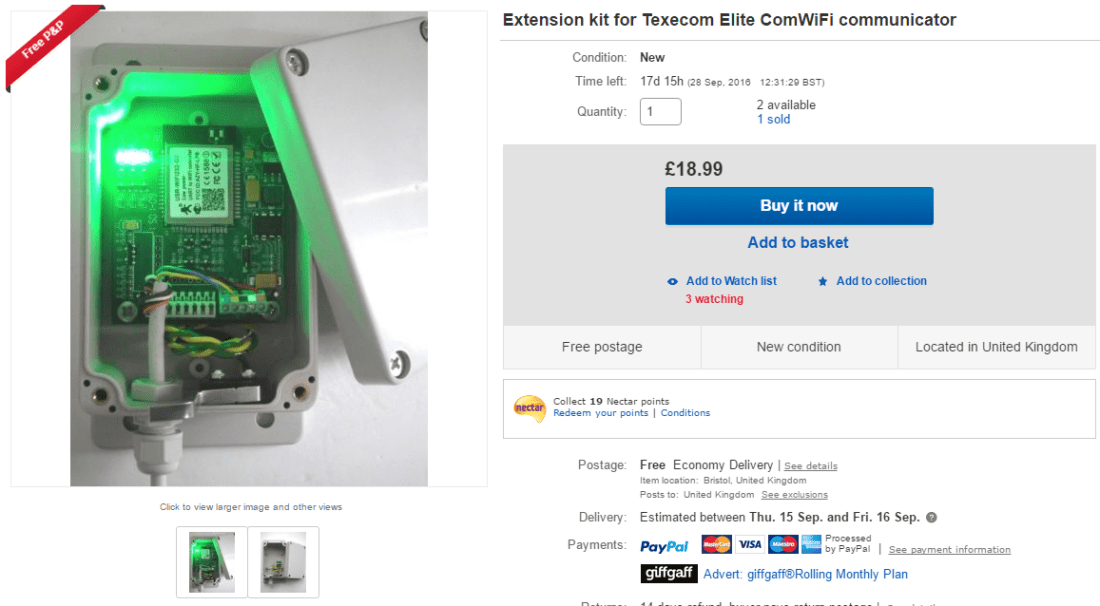
There are various expanders available, including simple wired zone expanders as well as the wireless ones. There are two wireless ones and the only difference is the number of sensors supported – either 8 for the 8XP-W or (you’ve guessed it) 32 for the 32XP-W. The latter is quite a bit more expensive so I found an 8XP-W on ebay for a reasonable price (about £40) although it’s around £65 new:

texecom-ricochet-premier-elite-8xp-w-gcd-0001-1140-p

After all the effort I have gone to so far to keep everything tidily inside the main steel casing it is a bit irritating to start having extra boxes on the wall. However there doesn’t really seen to be an alternative short of having the Ricochet box somewhere else in the house on the end of a wire.

Installation is pretty simple – just a matter of wiring up a 12V supply from the main panel, and connecting it in to the network connectors on the panel. The 48 panel only has one of these, but the connections are quite flexible and you can have various devices in serial and parallel. The main keypad is also connected to this. Here is a picture post-installation:

IMG_20160501_220534

There’s a small amount of configuration to do in Wintex, but make sure that you have uploaded it back to the panel before doing anything more. The key thing to do (which I missed intially) is to switch on the radio / Ricochet options in the ‘Edit Account Details’ screen and ‘Panel Info’ tab:

accountdetails

Once you’ve done all this then the expander should be available  for use. If you look in the zones screen you should see the wireless zones appear as such, with the code ‘XP1’ referring to the first expander and each device labelled ‘D01’, ‘D02’ etc:

zones

Once this is all done you can start adding devices. This turned out to be the most frustrating part of the whole thing and this is due to the fact that Texecom have changed the procedure for doing so and it is not very intuitive. The main thing to say here is to read the manual which comes with the expander very carefully, as this does spell it out.

The first thing to say is – ignore completely the ‘Learn Ricochet’ option in the engineer’s menu, as this will cause you no end of trouble (I learned this the hard way) and the manual tells you not to. What you have to do is firstly switch the sensor into learning mode. I used a PIR and a shock / door contact sensor and the procedure is different for each. The instructions tell you what exactly to do.

Then you need to select the zone that you want to program using the keypad from the engineer’s mode. So for my first zone, I selected ‘Zone Setup’ and then scrolled to the first wireless zone which is listed as Zone 009 XP01,01. There is a detailed flowchart in the manual which you have to follow exactly, and the bit where I got stuck was that you have to press ‘reset’ when the zone is displayed, then the screen shows ‘learning…’ with a countdown. Some of the sensors (the ‘autolearn’ ones) only will teach in for a brief period after powering up. So I’d recommend standing by the panel and snap the battery in to the sensor as soon as you see the ‘learning’ message.

The other tip is to install the ‘Ricochet monitor’ software alongside Wintex (as usual from the Texecom website). When you have an active Wintex connection you can call this from within it, and then it shows you a nice graphical representation of your sensors plus loads of diagnostic information. My network is pretty simple – 2 devices – but if you had a complex one I’m sure that this would be very helpful.

Now it’s all in and working I’m pretty happy with it. I may well expand the system with some more sensors in due course and there is a really good range of them including smoke detectors. I’d recommend getting the 32 zone expander if you can find it for a good price just to be on the safe side because you could use up the 8 quite quickly if you have a big system. the other thing I’m interested in is the range, as I have a garden shed which would benefit from coverage.

ComPort+ Update

As per the last Texecom post I had installed the new ComPort+ PCB into the spare header on the alarm main board. This in conjunction with the new v3.01 firmware gives another serial port. There is obviously a demand for this for Texecom to do it, although I would have thought for most people two would be enough! Still I am very grateful for it, because I have found a need for just this.

As described in previous posts, I have the GSM board installed on one port, and I have been using a second for configuration and monitoring using Texecom’s Wintex software. This is probably worth a post of its own, but it is an extremely useful and comprehensive software package which Texecom have as a free download and makes configuring the panels very easy.

I have also been experimenting with home automation integration. I have a Vera Lite which I bought a couple of years ago and I use it in conjunction with a number of Fibaro  devices (mostly the in-wall dimmer units). I haven’t really made the most of these yet although they have been handy for dimming some lights and linking together table / wall lights. Someone on the Vera forums gave me a copy of a plugin he had written to integrate the alarm, so that you can read the status of the various sensors in real time and also trigger events based on whether the alarm is set or unset. This uses another serial port, so now I can have the GSM dialler, the Wintex connection and the Vera connection all at once.

I must say that overall I’m not hugely impressed with the Vera – it is rather out of date now and quite slow in use. In particular the response to the events from the alarm is rather delayed. The UI is rather old fashioned and although they have done a newer one it is not reported to be working brilliantly and in particular does not work with the plugin. I have been in contact with someone lately who is using Homegenie which I haven’t come across before and which looks very interesting. So I’m going to look further at this although I’ll need a USB Z-Wave stick to test it out.

The other change which I’d recommend is that I have changed from using the small USB converter board to a simple cable terminated in header connectors to the pins. I probably should have done this the first time, but it means that there is more space inside the casing now. I used these but there are numerous other examples on ebay. However it’s worth noting that these are not FTDI based and so can’t be used with the flasher board.

USB serial

For reference the colour coding is:

Red – VCC
Green – TXD
White – RXD
Black – Ground

So when connecting to the Texecom the order is:

Pin 3 – Black
Pin 4- Green
Pin 5 – White