Programmer details

As promised I’ve taken some close-up pictures of the programmer PCB. The chip is a MAX662A and the capacitors are connected to it as per the datasheet. I’m afraid that these aren’t great quality pics because I couldn’t get the light right, I will get some better ones and upload them in due course.

I’ve not done anything to try and work out a schematic or pins assignments as yet. However I am pretty sure that I was barking up the wrong tree with pin 1 on the serial connector. Whilst it does have 12V applied to it via the output from the 662 I don’t think that this is needed for the flasher to work.

I’ve had a useful discussion with someone who makes these cables up and it appears that the key thing you need to make them work is the FTDI chipset on the serial controller – which is presumably what the official cable uses.

I’m going to have another go at flashing the firmware at the weekend so will post the results.

Texecom Firmware Flash – Progress

After a brief detour into heating control I’m back to talking about my Texecom adventures. I will as promised come to the more detailed software side of the heating project soon. However, with the Spring weather coming I’m feeling keen to start taking on some new projects so I’m back to thinking about upgrading my Premier Elite to v3.01 (it’s already gone up from v3.00).

As some commenters have pointed out, one can buy the firmware flash interface from www.cctvcentral.co.uk for a good price at the moment:

Capture

And they also are the only place anywhere that seems to be selling the ComPort+ accessory which gives you an additional serial port output using the on board communicator output.

comport

These need more discussion and I’ll come to this in another post. As you will see I had to buy 5 of them… so if anyone wants one of my 4 spares for a nominal fee to cover costs please let me know.

Anyway I took the plunge and ordered them all, and they arrived last week. The service from cctvcentral was pretty good, as the firmware flasher got damaged in transit and they sent me out another very quickly.

I spent a couple of hours this afternoon with the firmware flasher, but unfortunately so far have met with failure.

I connected everything up as per the instructions, and I have learned a few things. First of all, this is the first time I had tried powering the whole panel down and one of the problems doing this is that it sets off the tamper alarm on the external siren. I have a Texecom Odyssey 1 which  I installed some time ago. It is quite smart for a bell box, and one of things you can do is temporarily disable it if you are working on it. You can do this by using the engineer utilities to switch the strobe on 3 times in 30 seconds. This worked quite well, although it resets itself when you put the power back on. I’ve come to the conclusion that it’s impossible to do any kind of work on alarms without making a dreadful racket.

I’ve also learned that the Texecom firmware software only recognises FTDI serial ports – presumably because that’s what is in the genuine product.

However, on running the software and trying to flash the panel… nothing happens. It just gives an error message saying ‘board not responding correctly’.

I’m a bit stumped by this – I’m sure that the pinout is the same for the serial port and the software recognises it. I’m quite sure that I’ve connected the ribbon cable to the alarm board properly.

The only difference between my home made cable the real one is the first pin – which on the board gives 12V out. Looking at the flash interface, the corresponding pin is linked to a couple of pins on the flash board including a capacitor or two. So it must be doing something… but what? I’m really not sure what I should do about this, as unless I can get hold of a real Texecom flash cable I can’t know what that pin is for.

So all in all, not good news at the moment. I have the flash board… but I can’t use it. And I really do not want to be spending £40 on a genuine Texecom cable after getting this far! I have seen people on ebay selling third party copies which they say do work with the interface, so I might have to resort to getting one of these. It seems a shame though… I’m sure the solution is pretty simple but at the moment I have no way of finding it out!

Any comments or thoughts would be welcome. I will post some hi res pics of the board (including the all-important underside) shortly.

ComGSM update – success at last!

I have now succeeded in getting my ComGSM substitute to work. I’m grateful for the suggestions and advice I’ve received.

I have come to the conclusion that the TC35 board I originally bought just won’t work in this situation. I can’t really come up with a good reason for why, but as described in previous posts it doesn’t function correctly when connected to the panel. I think it does now work though so maybe I’ll find a use for it in another project.

I have now connected up the SIM800L module along with the voltage regulator and it worked perfectly first time. It is clear that this is a much more up-to-date module, being a fraction of the size of the TC35 one. It also uses a micro-SIM rather than a full size one which is handy. It is possible to insert the SIM the wrong way round though, which caused me some consternation until I realised it.

After some rough testing I’ve now permanently installed the two boards inside the metal casing, with the antenna fixed to the outside. I’m very pleased with the end result which is very ‘stealthy’ and actually to my mind is much neater than the official Texecom unit.


IMG_20151129_124104

Here is the whole cabinet, with the SIM800 module next to the main board on the right and the regular board hidden behind the bundle of sensor cables (note the incredibly bright green LED!). The antenna is on the top with the black cable just about visible.

These show the detail of the antenna, regulator and SIM800 board.

I then configured the panel with COM1 as the GSM module, and much to my relief after restarting the panel saw this in the ‘Online Status and Control’ window in Wintex:

Wintex

The bottom right shows that GSM signal strength and bit error rate as both being normal. The ‘online’ doesn’t mean anything as it says this even when nothing is connected.

As usual there is a huge amount of configuration you can do, and this is contained in the manual for the real GSM unit. It is wise to tone down the notifications, since as default you will get an SMS message every time the panel is armed or disarmed and it seems to store a backlog. When I first got it working I got loads and loads of text messages for the last week or so.

I need to properly test that it will send me a text if the alarm goes off but I’m sure it will work. You can also send various commands using SMS, but the issue I have with this is that you need to prefix them all with your code which means that if anyone got your phone they could easily read it out. However this is in reality rather unlikely.

I use giffgaff for the mobile phone service, mostly because I use them for all the other phones in our house as well. I’ve found them to be very good and I’d definitely recommend them.

So I am happy that finally this project is completed and at very little cost. I’ve developed the capability of the alarm and it does now stand alone in the event of a power failure etc and can get to the outside world without relying on the Internet.

So… what’s next? Well, I am getting interested again in intelligent heating control systems and have recently ordered some new bits, so will post about this when I have some time. In the mean time, if this interests you I’d thoroughly recommend Andy Carter’s blog on the subject which I’ve found a mine of useful information.

Premier Elite v3.00 Firmware

Visiting the Texecom website today I’ve made the exciting discovery that the firmware for the Premier Elite panels has had a major upgrade from v2.11 (which is what mine shipped with) to v3.00

Now I’m a firmware junkie – doesn’t really matter to me whether I want or need the new features, but I just want to be on the latest version. So whether it’s TVs, microwave ovens, dishwashers or guitar amps I’m always interested in getting the newest software release.

Texecom provide a very useful summary of the changes here

From a initial look through, much of it is expansion and improvements rather than major new features but one thing particularly caught my eye. Since I’ve been playing with these panels I’ve thought that I’d really like 3 COM ports – one for the GSM interface (when I finally get it working), one for integration with the Vera smart home controller (more of this in another post) and one for a permanent COMIP connection. This is apparently available on the most expensive panel but I didn’t think of that when I bought it.

Anyway it seems this new firmware allows COM3 to be accessed via the existing communication port – confirming my suspicion all along that it was just a COM port in disguise. It will require a breakout board which no doubt one will have to buy from Texecom:

comport

Although judging by this picture it will simply connect out a few pins – so maybe it will be possible to identify which pin is which and connect directly to it and I am worried that this new board will be expensive.

The other problem is that one cannot simply flash the new firmware using a COMIP or USB-COM which is a bit of a pain. The firmware is held in flash ROM, but they seem to have left the programming chip off the main board and so one has to buy the ‘CDH-001 Firmware Flasher’ which is going to be about £30 from the usual sources

Premier Elite Flasher Interface

Looking at this picture really makes me unwilling to pay £30 for the privilege – it is clearly just a MAX662A flash programming chip plus a couple of capacitors, a switch and a button which can’t be worth more than a few quid. However without knowing the pinout of the programming port and without being able to study one of these I’m a bit stuck. I’d love to be able to DIY one of these… but I suppose I may have to grit my teeth and stump up if I want to get the upgrade. I suppose if you are an installer you make your money back after the first job but for me the ‘cost per use’ is very high. If only they showed a photo of the underside!

To make matters worse the above adapter still needs the USB-COM to work, but at least I already have one of those.

If I do get one I’ll analyse it and post the results… or I could just stay at v2.11 but I’m not sure I can tolerate that now I know I’m out of date.

In other news I’ve now got all the bits from China so will try again with my ComGSM DIY effort and will post the results.

Good news & bad news

With thanks to a commenter on a previous article, I’ve had a close look at the ribbon cable which connects the TC35 module to the UART board. After a bit of fiddling with the (tiny) clamps which hold the cables in I was able to release the cable. At least one of the contacts appeared damaged, so I trimmed the end off each cable with a sharp pair of scissors and reconnected it. This picture shows the two boards disconnected with the ribbon cable in the middle. Normally the two boards are on top of each other and I imagine that the ribbon is under a bit of strain.


tc35

Initially there was no change – but then I tried reversing the TX & RX pins (ie connected TXD – TXD rather than TXD – RXD) and all of a sudden- success! I can now control the module through AT commands using my new USB device.

backfromthedead

So thinking I had solved the problem, I rewired the cable to the alarm panel (swapping TXD & RXD) and tried it – but once again with no success. I’m not quite sure what I’m doing wrong, or I suppose it might be that there is some other reason (maybe incompatible voltages) why this unit doesn’t work. I did wonder if it was because my SIM has no credit but it should still report signal strength and it does so if I try sending AT+CSQ directly.

So if anyone else out there is struggling with one of these modules – try trimming the ribbon cable and swapping over the TXD & RXD pins.

Meanwhile I have received the new board from China – which is tiny by comparison with the one I have. I know from Andy that this definitely does work, so I’m now waiting for the regulator board to arrive and I’ll give it a go.

Dead end… but not all bad news

Unfortunately it looks like the phone module I bought either doesn’t work at all, or there is some secret to using which I’m not aware of.

I’ve used the USB serial adapter (see below) to have a good probe around the various pins and try as I might I can’t get it to give any kind of response. I’ve tried various baud rates but there is no sign of anything coming back from the device. I’ve tried swapping the TX & RX pins over so that I am connecting TX to TX. This seemed a bit better in that I got an error message coming back from the serial console (UART overrun) but other than that no signs of life.

This is not helped by the lack of documentation. I will try contacting the Chinese seller but given how long I’ve had it (I got it in April) I don’t think I’ll get much back.

However there are two bits of good news:

i) The small USB serial interface and breakout cable is very nice and I’m sure I’ll find it useful in future

ii) I’ve had some very helpful comments from Andy (see older posts) who has bought a different module and got it working. So I’m following suit.

I’ve ordered these from ebay:

SIM800L-V2-0-5V-Wireless-GSM-GPRS-MODULE-Quad-Band-W-Antenna-Cable-Cap-M105-TopDC-Buck-Step-Down-Converter-DC-5A-Regulator-Voltage-Current-Adjustable-DE

The left is a SIM800L GSM module, and the right is a ‘DC Buck’ regulator. The GSM module looks much smaller and nicer than the one I have, and the reason for the regulator is that it needs 5V and I’ll need to step down the Aux power output from the Texecom panel which is 12V.

Andy reports that everything works fine with the panel and these modules, so I’m very pleased to find the concept is proved and I’m looking forward to trying it for myself.

Meanwhile if anyone has any idea about how to configure the TC35 I’d be glad to hear them.

Texecom Installers & Software

I’ve had a few queries about how to download the Wintex software and other information about these panels. Texecom have changed the way they deal with this recently, and you now need to register as an installer before you can download anything.

This can be done quite easily by clicking a link on the front page of the website where it says ‘security professionals register here’. Once you have done this you can get access to the downloads which include the various manuals and the Wintex software.

Whilst I may not be a professional as such… I do see myself as an installer and I’ve now bought quite a bit of their kit so I hope they won’t object!

ComGSM – not so easy as I thought

Unfortunately things haven’t gone quite as I had hoped, although I’m hoping this is more of a hiccup than anything else.

I have learned a few things about this GSM module:

Once you have installed a SIM you need to power cycle it before it will register

There are several LEDs on it – one of which is for power, and other for signal. This blinks very slowly before the SIM is registered, and then rapidly once it is registered.

I am not quite sure whether the pins are labelled properly

Having done a lot of fiddling around I have not been able to get any response out of the GSM unit by connecting it to the alarm panel. It should be showing a signal strength which it reads out from the module but it’s not showing. Similarly I can’t get it to send any kind of messages so there’s obviously something up.

My instinct is that it is not communicating at all, and there is something wrong with the interface between the panel and the module. The next thing to do is to try and interface with the module itself. I didn’t have anything suitable so looking on ebay I found this:

 usb (2)

I liked this partly because it was cheap (£2.70) and also because it came with a short cable as shown to connect up the individual pins. It has arrived, and so the next thing to do is hook it up to the GSM module and see if I can get any communication going. This will let me confirm that the pinout is correct, and also what the baud rate etc should be because the alarm panel is expecting 9600 8-N-1.

I’ll post again once I’ve had a chance to test it.

ComGSM update

After writing back in April about my ideas of using an off-the-shelf mobile phone module as a ComGSM I’ve not made much progress since. I did order a suitable unit from ebay direct from China, and after a few weeks it arrived.

I eventually got one of these:

TC35

http://www.lctech-inc.com/Hardware/Detail.aspx?id=a0678f46-a020-46ab-b02e-2d799eecdf1e

I took a few photos myself but the light is a bit odd and it looks exactly the same. Predictably, there are no useful instructions with it at all, so I’ve had to make a few guesses.

It has a standard pin header on the side, which is labelled on the board from left to right as VCC, Tx, Rx and GND. There is also a power supply connector block with two screw terminals labelld + and -. This is on the left of the picture. I did find reference in the brief information I could find to its standard settings being 9600baud, 8 bits, no parity and one stop bit. This is a pretty standard configuration and the same as I used for my tests described in earlier posts.

So in the end I thought the best thing to do was take the plunge and connect it up, and see what happened. I made a link cable up out of another old motherboard cable, and wired the power into the Aux 12v supply available on the main board. This isn’t a great picture but shows everything lashed up. The antenna is out of shot but just dangling on the antenna wire at the moment.

gsm2Here I learned some more important lessons which unfortunately cost me some time. After wiring it in I tried to connect using Wintex but I couldn’t make it work. I was really worried that I’d blown something up by connecting the GSM unit and after a lot of fiddling around I finally realised that I had simply got Wintex configured for the wrong type of panel (Premier 48 rather than Elite 48)!

Once I’d got this working, I then found that all of my sensors were dead and thus I once again worried that I’d broken something. Looking closely at the board I saw a new red light beneath one of the PCB fuses for the Aux 12v supply. I had obviously shorted out the supply when wiring the GSM board at some point. I was quite impressed with the attention to detail in the design, as having a red light under the fuse immediately showed me what was wrong. After replacing the fuse all was well again. There are several very bright red lights on the GSM board itself as well.

I’ve not been able to do much more testing as I’ve not yet put a SIM with credit into it. However, I did configure COM2 for the GSM module and on running Wintex saw the following:

GSM

So it does appear that the unit is recognising the GSM unit – hence GSM status ‘Online’ in the bottom right. The signal strength is effectively non-existent but that’s not surprising given that there is no working SIM in it. Also I’m not getting any errors that the COM port won’t initialise, which you do you get if you try to configure the module with nothing actually present.

So this all looks good… next thing is to get some credit on the SIM and try sending some messages!

Possible DIY alternative to ComGSM?

I’m feeling on a bit of a roll now… and I think I might have found another DIY means of adding functionality to the Texecom Premiere Elite panel. I’ve always been interested in the idea of adding a mobile phone dialler to the panel to send a text message when the alarm sounds.

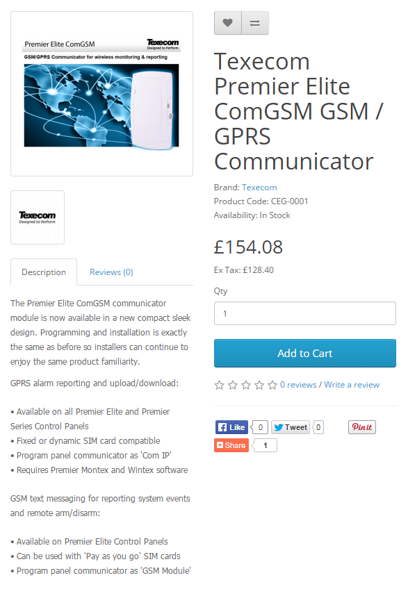
First thought was to buy the genuine Texecom add-on, called (predictably) the ComGSM. However, once again there were a few difficulties with this. The unit itself is readily available from the usual sources (eg www.cts-direct.co.uk):

COMGsm

Firstly, you won’t be surprised to learn that I think that this is quite expensive. Secondly, I didn’t really like the way that it was an external box when there is lots of space inside the existing alarm housing.

I looked at some alternatives. You can get on ebay some boxes which take a SIM card, and when triggered send a standard text message to a list of numbers. These are cheaper, and smaller and so easier to install. However, they looked awkward to configure and did feel like a bit of a clumsy solution. It would have been straightforward to trigger it using one of the panel’s outputs though.

Once I started reading the instruction manual for the panel a bit more I preferred the Texecom solution. This was partly because of being able to configure everything easily through Wintex, and also because when it is triggered it sends a much more detailed text message with details of which zone is triggered etc. It also allows a limited control, so you can disarm the alarm and get some status reports by sending text messages as well.

After having some success at getting the serial interface to the panel working (see earlier posts) I decided to investigate a bit further what the panel was doing when the ComGSM was installed, and how it was communicating. The genuine unit is installed by connecting to one of the two serial ports inside the panel, and as I learned when doing the USB interface these are operating as entirely standard ports.

My first thought was that the panel  would send some kind of encoded commands to the ComGSM which were then translated into control of a phone dialler. I thought that it might be possible to use the Raspberry Pi as a ‘man in the middle’ to translate the commands from the panel and then get the Pi to control a dialler. This seemed a tall order, but worth investigating as it would cut the cost down.

As a start, I configured the panel to have a ComGSM installed on the second port, and plugged in the USB-serial adaptor to listen to what it was doing. This is another setting which is buried in Wintex, this time in the ‘Communicator Options’ screen under the ‘Programming’ menu:

CommsMenu CommsOptions

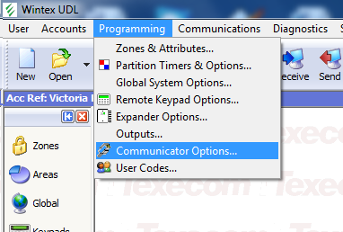
You can set a whole range of different options for either of the built in com ports as Texecom make a whole lot of different ones. For the purpose of this experiment I set it to ‘GSM module’ which is the one for the ComGSM.

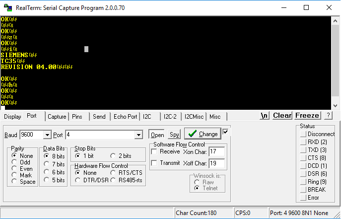
I then ran a simple serial terminal program to see what was coming back. At first, I got a series of garbled characters but they repeated regularly. I tried a few differnet combinations at random, sticking to 8 bits, no parity and one stop bit (aka 8N1, the most common configuration) and eventually on selecting 9600 baud, and to my great surpise, I saw the following coming from the panel:

+++

ATZ

ATZ

ATZ

ATH0

These commands were sent in a repeating sequence. These commands form part of the very well known AT command set, which has been used for modems since the 1980s. It used to be known as the ‘Hayes AT’ command set, named after the pioneering modem company which first developed it. I remember using this myself back in late 80s and early 90s, at which time it was not uncommon to control the modem manually using AT commands rather than having it done automatically through comms software. You would send the command ‘AT’ to the modem (short for ATtention) and get back the response ‘OK’. Other commands could be appended to the AT – so ATDT0123123123 would cause the modem to Dial with Tones (rather than pulses) the number. Over the intervening years, the command set has been developed to include a whole range of other commands, and this includes for dealing with mobile phone connections and text messages.

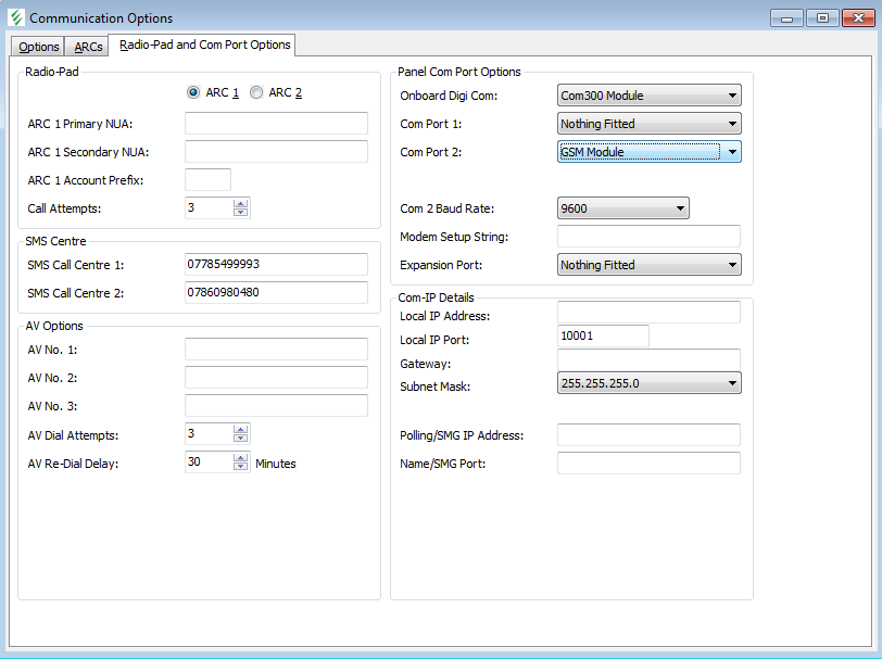
The commands above – +++, ATZ and ATH0 are fairly standard initialisation commands, to reset the modem (ATZ) and hang up any calls (ATH0). I tried sending back the expected repsonse – ‘OK’ – and was pleased see the panel respond with more commands including some newer ones which were for listing out and retrieving stored text messages. This shows some of them:

Realterm

The formatting is a bit strange, but you can see the first commands towards the bottom, and then some more wrapping round including AT +CSQ which is a request for signal strength, and AT +CMGL=”REC UNREAD” which lists out unread text messages. There is a function

So from all this, my conclusion is that the panel is sending out entirely standard messages, so there is no need for any translation at all. I now think that it should simply be a question of finding a GSM modem module and connecting it directly to the panel.

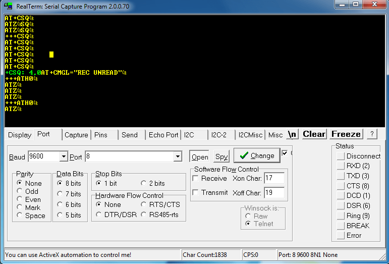
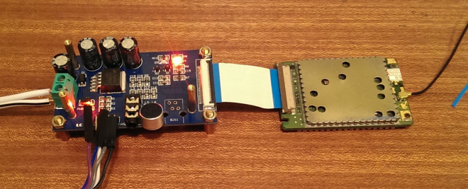
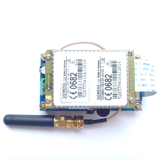
There are quite a few of these to choose from, but in order to keep costs down I decided to order one directly from China via ebay. Many seem to be based on a Siemens module, and they come in all shapes and sizes with various interfaces. However i settled on this one:

2015-04-25 20_32_24-GSM SIEMENS TC35 SMS Board LM2596 UART Wireless With Antenna Voice Module _ eBay

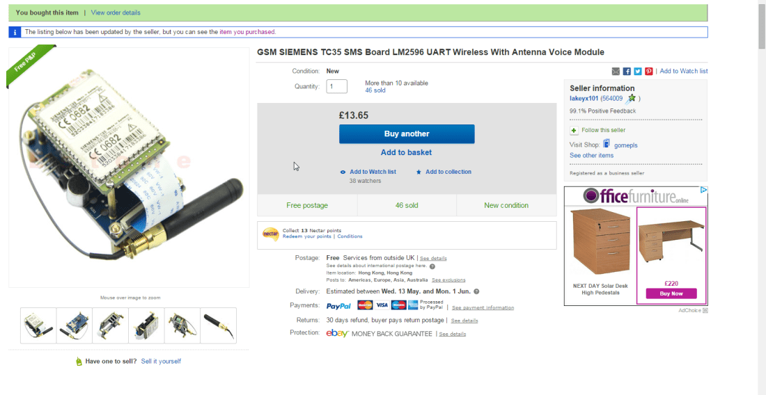
It has a simple serial UART interface so should be able to speak directly to the panel. It also had the advantage of being pretty cheap, although I did have to wait a few weeks to be delivered. It’s only just arrived, and once I’ve had a chance to play with it will post an update. I am hoping that if if works I can mount it inside the casing with the antenna bolted to the top. For me this will be a much neater and more elegant solution than the real one!
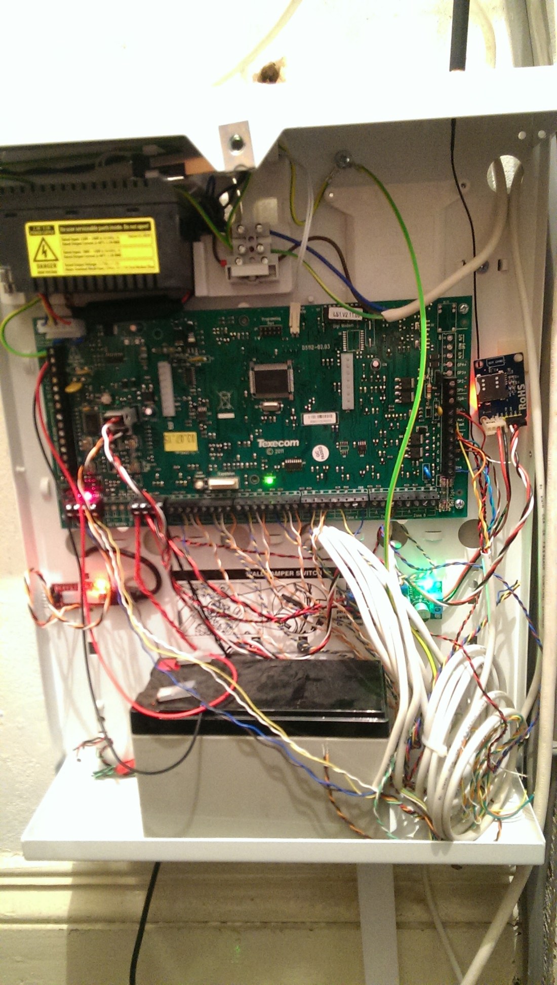
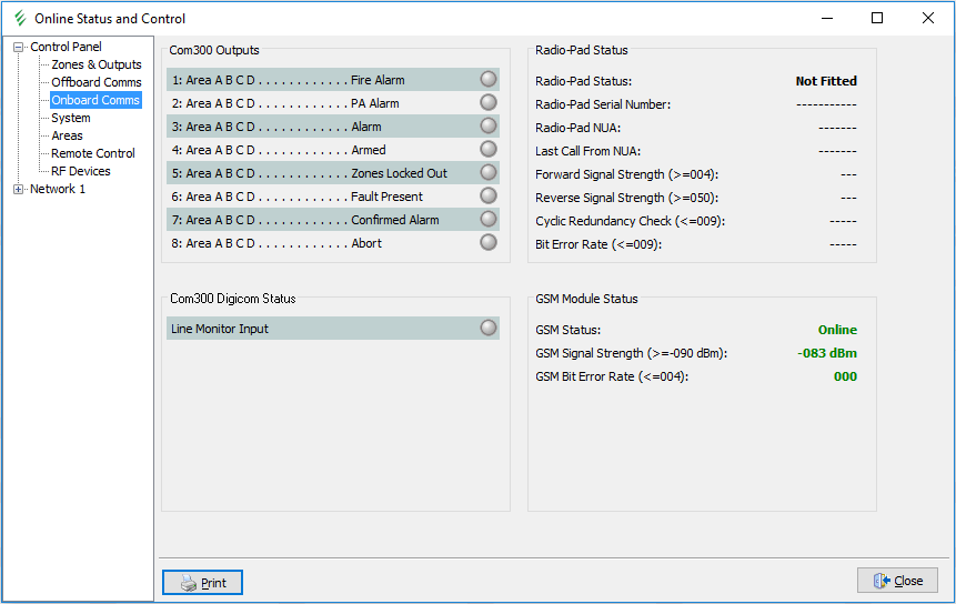
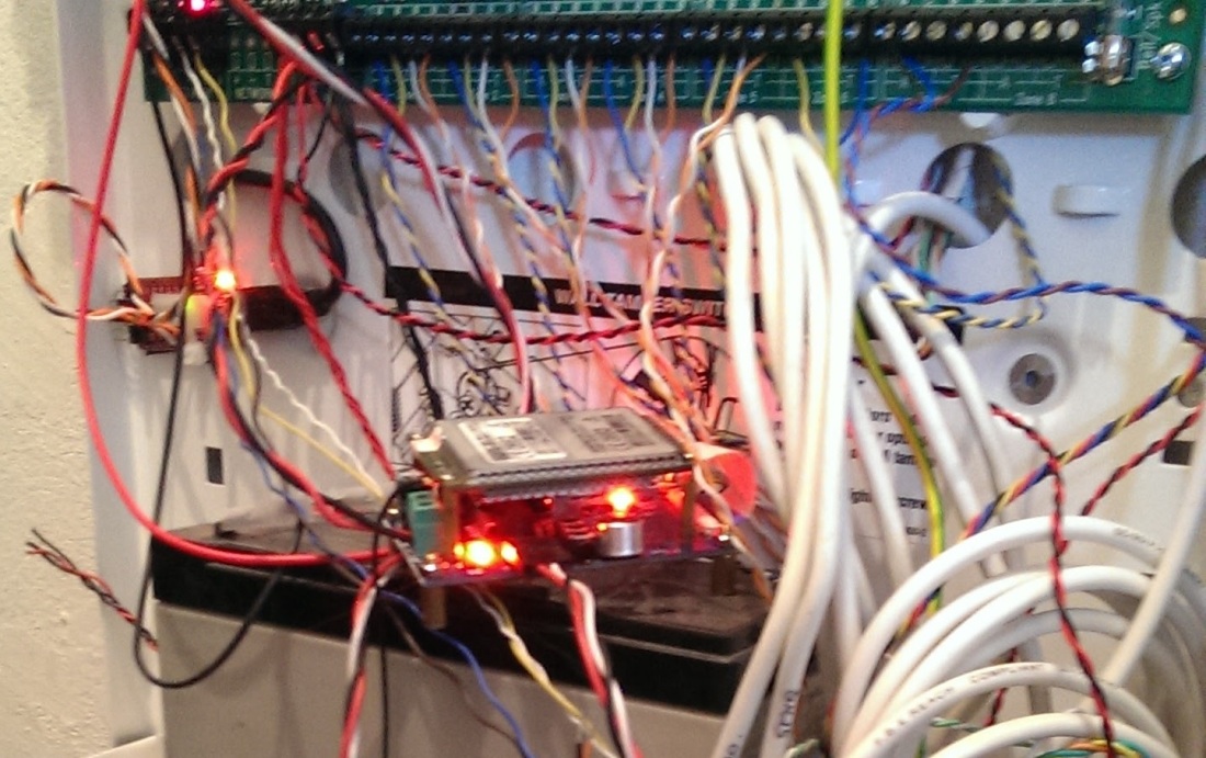