I have written a few times about my interest in home automation and in particular my use of the German ‘FHEM’ system to link it all together. One thing I have wanted to do for a long time is get the sensor data from the alarm system readable in FHEM to do useful things with, such as turning on lights when PIRs trigger. I would love to be able to do this in software, and whilst I have most of the information I need I’ve not had the time and space to sit down and tackle the job.
We have relatively recently got a cat.

However, we don’t have a cat flap and so we have to open the back door to let her out, and leave it open so she can get back in again. This causing problems with the thermostat for the underfloor heating, and so really I want to switch the UFH off when the door is open and the cat has gone out. This got me thinking about the problem again, as I have a sensor on the back door for the alarm (see earlier posts).
I have come to the conclusion that I’m not going to be able to do this in software, so I started thinking about hardware again. In a previous post I wrote about using one of the panel outputs to trigger an Arduino to throttle down the heating when the alarm was armed, and so I wondered if I could do something similar for zones or other things.
However, the Premier Elite 48 panel I have only has two ‘panel outputs’, one of which I was using. The 88 and 168 panels have more but even then only a total of 5. I thought I could just use the other one, but looking again at the manual I saw the ‘Digicom outputs’ header on the left hand side of the panel:
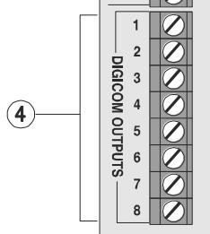
So here are a total of 8 outputs, and from looking at the manual and in Wintex it seemed that almost anything can be assigned to them. In the earlier post I wrote about the convenience of the ‘open collector’ nature of the panel outputs which means that the various different voltages that things run at (12V for the panel, 5V or less for the Arduino) don’t matter. The Digicom outputs on the other hand are ‘switched 0V’ which means that they are at supply voltage (ie 12V) and pulled low when activated. So these can’t be used for direct connection and some form of hardware interface is needed.
This is of course a very common issue and there is a lot that has been written about approaches to this situation. I read about various options but the simplest seems to be to use a potential divider in which two resistors are used to split the voltage and a tap is taken from the junction between them. In this case, the idea is to reduce the 12V to somewhere between 3V and 5V to feed to the Arduino. I’ll need one for each of the outputs, and it struck me it might be a good idea to have an LED as well to absorb some of the voltage and also allow for some hardware troubleshooting. To make the whole thing as neat as possible I decided to build the interface on some prototyping board and mount the Arduino in the same place.
There is loads of stuff written about how to calculate the values needed, but often it comes down to what you have to hand. I have a junk box with various components but after a bit of digging around I found some 3k3 and 2k2 resistors, and after putting an LED in series first and applying 12V I was getting about 4.2V at the junction, which seemed fine. I added a few other refinements including pin headers for connecting the Digicom and 0V lines, and I mounted the Arduino on the same board with connections in to each of the digital pins.
The result looked like this:


Not perhaps the neatest bit of soldering ever… and I have definitely learned a few things about using this type of circuit board. I used short pieces of wire to connect from the divider to the Arduino, and some wire links here made from component leads here and there. The pin headers on the left are in two sections. The LEDS are significantly underrun but they are quite visible when lit up.
The other thing to note (not easily visible above) is that the 0V line from the Arduino was connected to the 0V line coming from the panel to minimise the risk of spurious readings or other odd behaviours (otherwise the Arduino ground is via the USB to the computer, ie not common).
Final job was to install in the Premier Elite casing:

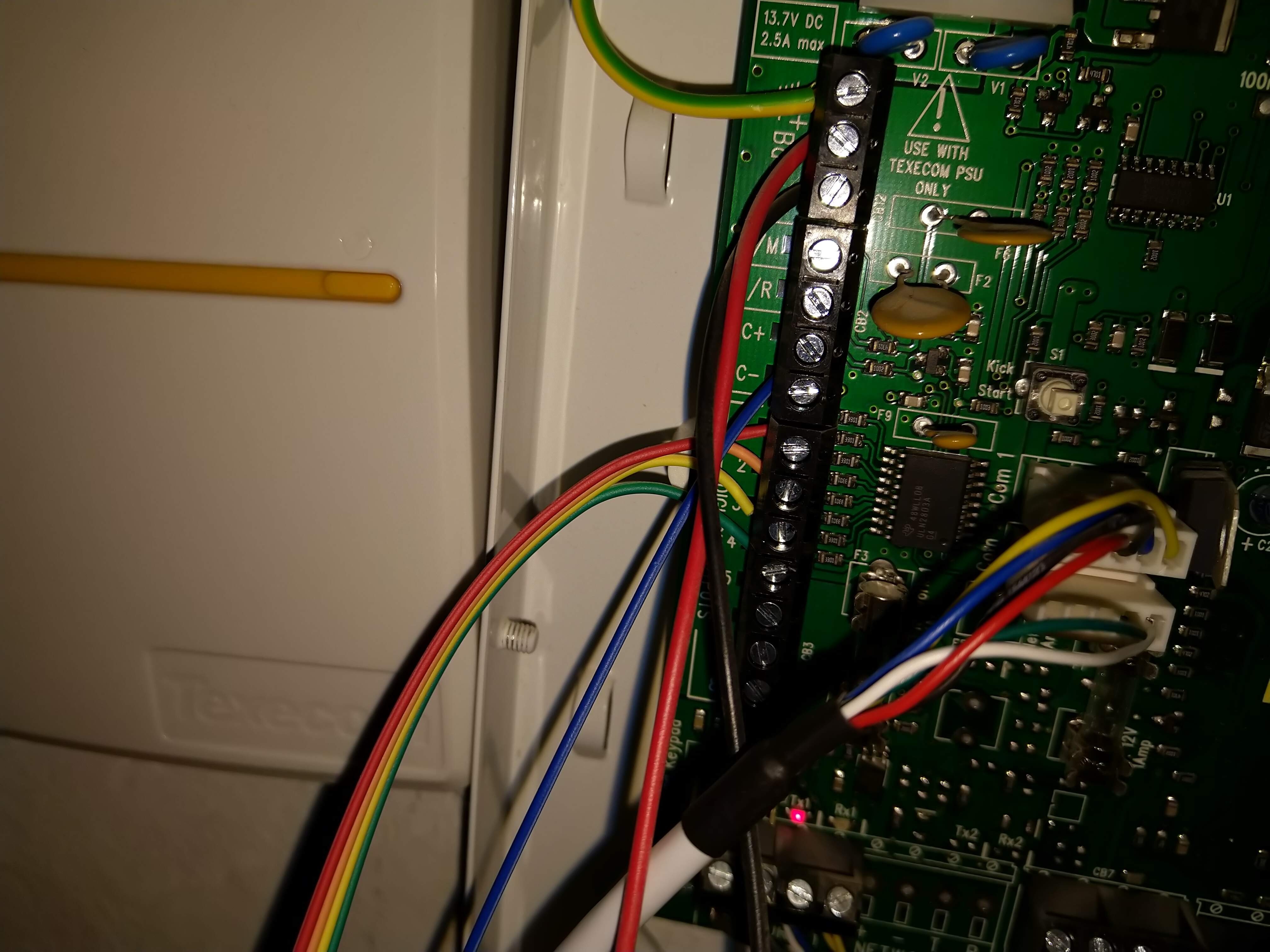
I used some short ‘Dupont’ cables to connect to the Digicom terminals, in truth these were too thin to work well so I tinned the ends with solder before connecting them to the terminals which helped make a sturdier connection.
I was very pleased to see some of the LEDs light up when connected, although it will need some configuration in Wintex to get them working as I want them to.
So the hardware is done… now on to the software!
