Integrating a BEOK BOT-313 Thermostat (Part 2)

Having installed the new thermostat as detailed in the last post it is working fine as a standalone device, but the configuration in FHEM is needed to get the value out.

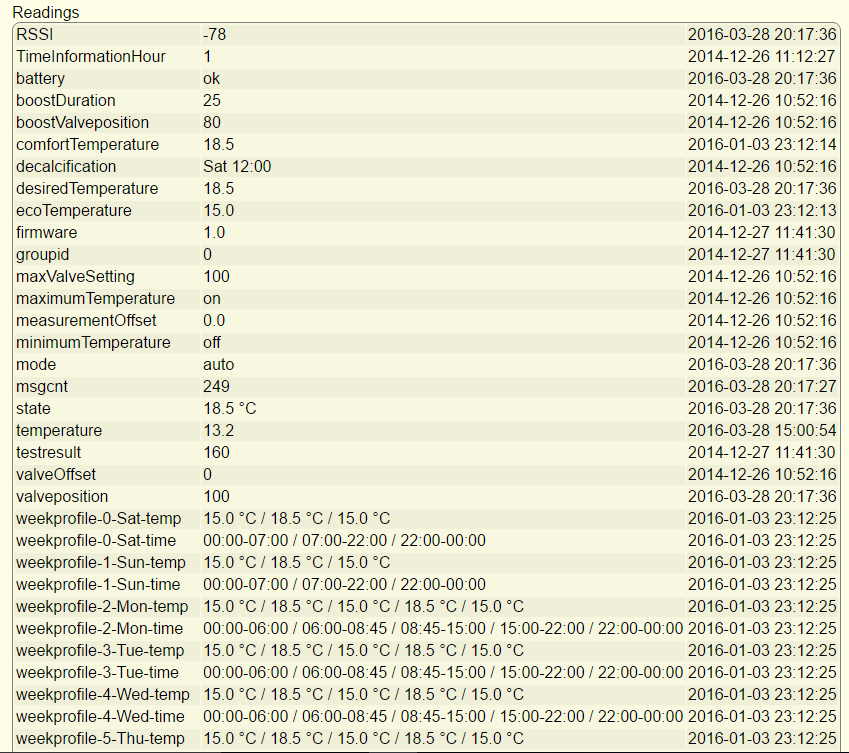
I’m always impressed by the amount of information you can get out of simple devices and this is no exception:

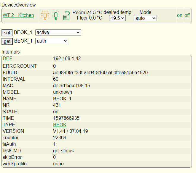
There are also loads of various readings you can get out as well, including a regular temperature reading which is great for monitoring:

You can also set almost any of the parameters, including the weekly profile and various other things.

What I needed to find was a way of stopping the heating from running when the back door is open. When the cat goes out the air temperature in the kitchen drops rapidly and it is pointless to run the heating until she comes back in.

There are a number of possibles, one of the most obvious is a ‘frost protection’ mode which many thermostats have and although there is a setting for this it’s not mentioned in the manual and doesn’t actually seem to do anything. I could actually have simply switched the thermostat off completely (which I tested and worked well) although this felt a bit over the top and would stop the temperature monitoring.

I settled on switching between manual and automatic modes, with the manual setpoint set fairly low (around 15 degrees). So when the door is open the setpoint drops and the heating switches off. You can see evidence of this in the green line on the graph above.

This is done in FHEM using notify events and some simple commands. It is simply a matter of ‘set BEOK_1 mode auto’ or ‘set BEOK_1 mode manual’ in response the event. This is done simply in FHEM using ‘notify’ events, one for the door opening another for the door closing:

To define this in FHEM I used the following:

define HeatingBackDoorClosed notify TexecomDigi4:reading:.off set BEOK_1 mode auto

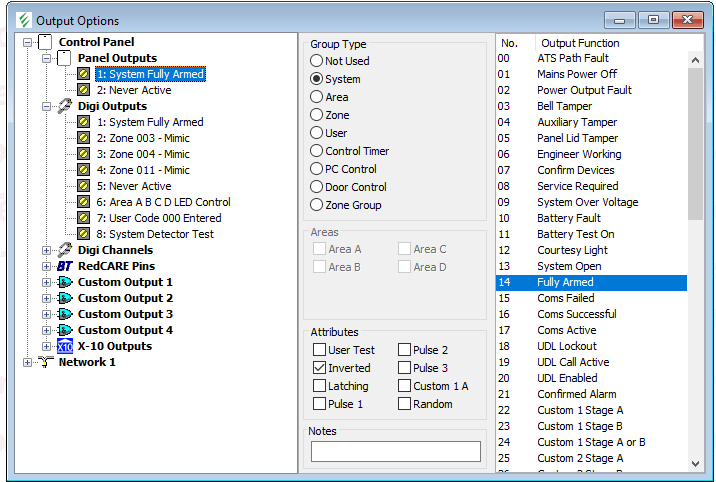
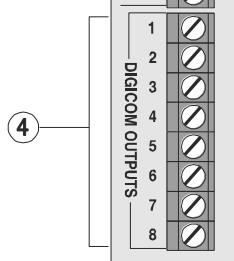
‘TexecomDigi4’ refers to the digital output, which is on when the door is open and off when closed. So whenever the door is closed, the trigger of the Digi4 to ‘off’ creates an event which sets the thermostat back to automatic mode. A similar one is in place to handle the door opening events.

I was pleased to find that this worked first time, and even with repeated and rapid opening and closing it doesn’t go out of sync. It has been far too warm lately for the heating to come on anyway and the cat has enjoyed long days in the garden but this is likely to change as we get into the Autumn.

So now I need to think of a few more use cases… and there are a lot of Texecom goodies to go at still.

Integrating a BEOK BOT-313 Thermostat (Part 1)

In a previous entry I talked about building a hardware interface to the Texecom panel with a few ideas in mind, but initially triggered by wanting to avoid heating the kitchen when the cat is out:

Less of a problem in the summer of course, but also a good time to play around with heating controls. I am still using FHEM as my central control system, basically because I have yet to find anything better. It does perhaps look a bit old fashioned now but it is very functional and still has a broad range of compatibility.

My kitchen underfloor heating is controlled by a solenoid valve, which when energised opens the flow to the heating pipes and calls for heat from the boiler. The original control was a Heatmiser Neo which is a nice system and ‘automatable’ – but only if you have the matching hub. In any case it doesn’t work with FHEM and I’m not sure how open it is.

My requirement was for a normal wall thermostat / programmer which could also be controlled remotely by FHEM and which looked the part. As it turned out, this was not easy to find or at least not without spending a lot of money. There are quite a few ‘wifi controlled’ thermostats out there which use some kind of an app, but most of them are standalone and not supported by anything much.

After a lot of digging around I came up with the BEOK BOT-313. This is a fairly typical low-cost Chinese import but someone has decoded the protocol and it is supported natively by FHEM:

Getting hold of one proved a little more complicated than I’d hoped. It turns out there are several different versions of this which are designed to work with a number of different heating types. I originally got one from Amazon but it turned out to be a version for use with an electric heater, and did not provide the simple relay that I needed. Instead it simply provided a Live and Neutral output. So whilst I could probably have hacked things together I eventually took a deep breath and ordered the correct one direct from China on Aliexpress. There are various choices but I got the 240v wired in version.

There is a lot of debate on the FHEM forums about different software versions on these devices, which are also sold under a variety of brands (Fluoreon is one but there are various others). However the safest thing seems to be to buy this particular one.

I have bought stuff from China before and so I knew what to expect but I was pleasantly surprised by the quick delivery, it did take a few weeks but that’s not bad given the circumstances. It was cheap too!

Installing it was fairly easy, it’s just a matter of connecting up the mains supply and the boiler terminals. You can use it as a standalone unit, but the value clearly lies in getting it on the network. Unfortunately this is not easy as you have to use the BOK app which is pretty ropey. The other thing is that it only works with 2.4GHz Wifi and it won’t connect if you have a 5GHz network on the same SSID, so I had to temporarily disable the 5GHz before it would pair. Once this is done you can switch the 5GHz back on again and it works fine.

So with the hardware in it’s a matter of configuring it in FHEM… so more in Part 2!

Interfacing and configuration

Having installed the interface board there are two stages to configuration. The first is to get the panel itself to trigger the outputs and the second is to interpret them in FHEM and trigger some actions.

The outputs in Wintex are located in a section labelled (helpfully) ‘Outputs’ in the programming menu:

There are a lot of different ways of configuring outputs as you can see. I was previously using the ‘Panel Outputs’ at the top, with ‘System Fully Armed’ being the trigger to throttle down the heating. However, I’m now interested in the eight ‘Digi Outputs’ listed underneath.

For each output there is a bewildering array of possible options – there are eight groups (system, area, zone etc) and each group has numerous other options. For example, the ‘user’ group allows triggering of output on a specific code. The level of detail is really impressive and pretty much anything you can think of is catered for.

My needs are quite simple, I want to trigger an output for system armed (for the heating), and for activation of the PIRs and back door contacts. This is done by selecting the ‘Zone’ group and setting the correct zone number.

The other thing to set is the ‘output function’ which dictates the behaviour. I want to read the status regardless of whether the alarm is armed so I have used ‘Mimic’. There are other ‘attributes’ you can set, I could have used ‘inverted’ which would have pulled the output high on trigger, but I can accomplish the same thing in the software at the other end so I left it alone. I need to think about what else I could use these outputs for, but for the moment I have assigned them to various of the zones around the house including the all-important back door to accommodate the cat.

Once the programming was sent to the panel, I was pleased to see the LEDs displaying what I expected – those corresponding to the PIRs went out whenever it was triggered.

I’m not going to go into great detail on the FHEM configuration, which is a little fiddly (but if you are interested please contact me and I’ll try to help). The Arduino has the ‘Firmata‘ sketch loaded and this is attached in FHEM as a USB device:

The various pins are made available for use (in my case pins 2 – 9) and you then define the pins you want to use as inputs as a separate device:

You can reference the reading of (in this case) ‘TexecomArm’ in logic which does things based on the condition. In FHEM-speak this is done using ‘notify’ events. I have used ‘notify’ events to switch on the main lights in some of the rooms when the PIR is triggered:

It looks a bit complex, but the relevant line is the ‘DEF’ at the top. The command is triggered when TexecomDigi2 (ie the 2nd Digicom output) reads as ‘on’. The event is to ‘set Hue_HUEGroup2 on’ which turns on a series of Hue lights in the room.

The only problem was that we watch films in the front room sometimes, and we turn the lights off. In that situation, you don’t want them suddenly coming back on again. Luckily, FHEM can also talk to various other devices I have including the home cinema amp (a Denon AVR-X2000). Therefore, triggering the output evaluates an ‘if’ expression, and it only triggers the lights on if the amp is off (or rather, if it is not on – ‘ne’ meaning ‘not equal to’). So if the amp is on and we turn the lights off, they stay off. If the amp is off (and therefore no-one is watching anything) the lights come on.

Although these are only small things, they really show the value of having as many data sources as possible and making things work together to really anticipate what you want. I’m really excited to see what else I can think of for this, and further expand how the panel and the rest of my devices at home work together.

Oh and concerning the cat… I now need to get a wifi thermostat for the underfloor heating that FHEM can address. I have a Heatmiser Neo at the moment but this isn’t supported, so I need either a Floureon or Beoks device instead. I’ll post further when I’ve got this working.

Texecom and FHEM interfacing

I have written a few times about my interest in home automation and in particular my use of the German ‘FHEM’ system to link it all together. One thing I have wanted to do for a long time is get the sensor data from the alarm system readable in FHEM to do useful things with, such as turning on lights when PIRs trigger. I would love to be able to do this in software, and whilst I have most of the information I need I’ve not had the time and space to sit down and tackle the job.

We have relatively recently got a cat.

However, we don’t have a cat flap and so we have to open the back door to let her out, and leave it open so she can get back in again. This causing problems with the thermostat for the underfloor heating, and so really I want to switch the UFH off when the door is open and the cat has gone out. This got me thinking about the problem again, as I have a sensor on the back door for the alarm (see earlier posts).

I have come to the conclusion that I’m not going to be able to do this in software, so I started thinking about hardware again. In a previous post I wrote about using one of the panel outputs to trigger an Arduino to throttle down the heating when the alarm was armed, and so I wondered if I could do something similar for zones or other things.

However, the Premier Elite 48 panel I have only has two ‘panel outputs’, one of which I was using. The 88 and 168 panels have more but even then only a total of 5. I thought I could just use the other one, but looking again at the manual I saw the ‘Digicom outputs’ header on the left hand side of the panel:

So here are a total of 8 outputs, and from looking at the manual and in Wintex it seemed that almost anything can be assigned to them. In the earlier post I wrote about the convenience of the ‘open collector’ nature of the panel outputs which means that the various different voltages that things run at (12V for the panel, 5V or less for the Arduino) don’t matter. The Digicom outputs on the other hand are ‘switched 0V’ which means that they are at supply voltage (ie 12V) and pulled low when activated. So these can’t be used for direct connection and some form of hardware interface is needed.

This is of course a very common issue and there is a lot that has been written about approaches to this situation. I read about various options but the simplest seems to be to use a potential divider in which two resistors are used to split the voltage and a tap is taken from the junction between them. In this case, the idea is to reduce the 12V to somewhere between 3V and 5V to feed to the Arduino. I’ll need one for each of the outputs, and it struck me it might be a good idea to have an LED as well to absorb some of the voltage and also allow for some hardware troubleshooting. To make the whole thing as neat as possible I decided to build the interface on some prototyping board and mount the Arduino in the same place.

There is loads of stuff written about how to calculate the values needed, but often it comes down to what you have to hand. I have a junk box with various components but after a bit of digging around I found some 3k3 and 2k2 resistors, and after putting an LED in series first and applying 12V I was getting about 4.2V at the junction, which seemed fine. I added a few other refinements including pin headers for connecting the Digicom and 0V lines, and I mounted the Arduino on the same board with connections in to each of the digital pins.

The result looked like this:

Not perhaps the neatest bit of soldering ever… and I have definitely learned a few things about using this type of circuit board. I used short pieces of wire to connect from the divider to the Arduino, and some wire links here made from component leads here and there. The pin headers on the left are in two sections. The LEDS are significantly underrun but they are quite visible when lit up.

The other thing to note (not easily visible above) is that the 0V line from the Arduino was connected to the 0V line coming from the panel to minimise the risk of spurious readings or other odd behaviours (otherwise the Arduino ground is via the USB to the computer, ie not common).

Final job was to install in the Premier Elite casing:

I used some short ‘Dupont’ cables to connect to the Digicom terminals, in truth these were too thin to work well so I tinned the ends with solder before connecting them to the terminals which helped make a sturdier connection.

I was very pleased to see some of the LEDs light up when connected, although it will need some configuration in Wintex to get them working as I want them to.

So the hardware is done… now on to the software!

Integrating Home Automation & Alarm

I have been thinking lately about improving my approach to home automation, and particularly in making better use of the various technologies I’ve got. I think one of the mistakes made in home automation generally is neglecting the ‘automation’ part. I’ve seen plenty of approaches which really just substitute one set of switches for another (albeit electronic). I can’t see much point in in switching lights on and off using a phone or remote when it’s much easier to do so using the light switch! So really what you want is a largely automatic system which anticipates your needs and does what you want without user intervention.

So far as I have written about before I already have a mixture of systems with MAX for heating (currently controlled using FHEM) and Z-Wave for which I have been using a Vera Lite. I have been using a 3rd party plugin which provided an interface between the Texecom panel and the Vera, but in spite of this I’ve never been that happy with it as a controller. The interface is rather old fashioned, the newer updates (so called UI7) have had a decidedly mixed reception and I’ve never really felt I understood how to program it properly. Whilst the UI looks pretty it was also rather clunky when you tried to use it.

I’ve written before about FHEM and whilst I know it’s not everyone’s cup of tea I have really got to like it because although it looks unappealing it gives you a huge amount of information and lets you do pretty much anything you want with a few command lines. I also think that it helps you understand a lot more about the devices you are using. So the obvious thing to do was to bring all my Z-Wave devices into FHEM and try to integrate heating and lighting and also build integration with the Texecom panel.

The key to all this is a USB Z-Wave adapter for my main server. These don’t come cheap and there is some choice. I eventually bought an Aeotec Z-Stick Gen5, which came recommended but pretty expensive at about £40.

aeotec-z-wave-usb-z-stick-526


There are others available, including the Z-Wave.Me UZB which seems rather cheaper. This should also work with FHEM and other software although the Aeotec seems slightly better established. The other and much cheaper option is to use an experimental method whereby CULFW devices can be set up as Z-Wave controllers. However this lacks some of the benefits of the proper controllers (including battery back up etc) and probably is not for ‘production’ systems just yet.

So far all has gone well. FHEM recognised the controller and configured it correctly. I had to ‘exclude’ all the devices from the Vera to reset them and then ‘include’ to the Z-Stick. You can do this either by physically taking the stick to the device and pressing the button on the stick, or else simply setting the Z-Stick into ‘inclusion mode’ from FHEM and then doing whatever is needed on the device.

I would recommend doing the latter, as then FHEM will automatically pick up and configure the devices for you. I now have a variety of Fibaro devices and a Minimote which are all available as devices in FHEM with a lot of detail about them. I have recreated a few scenes which I was using before (such as one which turns on a few table lamps in the front room).

Now I need to find a better way of integrating with the alarm. I am using an Arduino with one of the outputs from the panel to report whether the alarm is set or unset and therefore whether the house is occupied or not. I’m using this at the moment to trigger a ‘notify’ event in FHEM which sets the heating into low power mode and now sends Z-Wave events which turns off all the lights. What I would really like is to get FHEM to interface directly with the panel to read out the status of the sensors etc directly. I have been able to get some information about this so I am going to see if I can learn how to do this.

As always I’d be very interested to hear from anyone else who is exploring this kind of thing.

Using Fhem for Heating Control

Having discussed in previous posts my hardware approach to heating control I’ll now talk about the software.

The key to the whole system is FHEM which is a real discovery. As I’ve found before with the hardware, the Germans seem to have really got to grips with home automation. This system is open source and very mature, having been around for quite a long time and now being up to version 5.7. The problem is that at least initially it doesn’t appear particularly accessible or easy to use, but this is rather misleading. With a bit of effort invested you can get the system working well and it is incredibly flexible.

There is a good community supporting it, although it is predominately German speaking. Most of the documentation is too, but Google Translate has proved very helpful in navigating the forums and the wiki .

I won’t go into the basic setup, but you will need some kind of server (I am using a fairly old but extremely useful HP Proliant Microserver) and a suitable operating system. There are various ways to install Fhem which are detailed on the website and elsewhere.

So once you have a working Fhem system you can access it via a local URL and then the fun begins!

The basics are to get the interface installed and working. Fhem does have automatic mechanism for detecting and installing devices, which is based around a set of configuration files, they key one being fhem.cfg. In my case I am using a CUL device (as in previous posts) but there are various other ways of doing it. Some people have used the official MAX controller although it’s not much cheaper than the CUL and some difficulties have been reported. There are some other ways of getting CUL firmware onto cheaper devices but I haven’t explored these as yet.

What I really like about Fhem is that its basic structure supports a whole range of different devices (see the documentation for details) but it has a common approach to dealing with them. Also, whilst it is mostly based on configuration files the standard front end UI whilst basic is very effective.

So once you have a basic Fhem system up and running and your CUL or equivalent device has been detected – what next?

First thing to do is register all the MAX devices and pair them with your system. You will need to do this using the ‘learn’ mode on the devices and also by setting the CUL device to listen out for new devices.

You can do this by selecting ‘pairmode’ on the Fhem screen for the CUL device:

pairmode

This then sets it to listen for a short period of time, and you then need to set the devices to pair. What exactly you do depends on which device you have, and you’ll need to check the instructions. However, for most of the thermostats I think you have to hold down the ‘boost’ button for a few seconds and then it begins a countdown, which stops again once the pairing is complete.

You will then see the MAX devices appearing in your Fhem screens. The screen for each looks something like this:

maxscreen1maxscreen2maxscreen3

This screen demonstrates the strengths and weaknesses of Fhem, depending on who you are. For me this is great – lots of details, loads of options to play with etc. On the other hand you might think it looks overcomplicated and intimidating… in which case this probably isn’t for you.

All Fhem devices have settings (via the ‘set’ button at the top) and the pick list shows you what variables you can set. The ‘readings’ section shows the enormous amount of data you can extract from what is in reality quite a simple device. This includes the weekly ‘profile’ for each device – ie the combination of settings and times throughout the week. This is different for each individual thermostat which is good from a flexibility point of view, but not so good for consistency and ease of programming. There are solutions to this which I will come to in future.

So you should now be able to pair up all your thermostats, and the Fhem screens will allow you to see the measured temperature and make some changes. However, this isn’t much of a control system on its own and I’ll come to what I’ve done to tie it all together in future posts.

I know I’ve kept this quite general but please post comments or questions and I’ll try my best to answer them. There is a lot of info on the Fhem forums / wiki which are a good place to start if you are stuck.

Boiler Control using MAX hardware

So now I’ve got a number of MAX radiator valves around the house which are linked up to FHEM which is providing some monitoring and control. I’ll go into some more detail on the software side in another post. However, I realised that the amount of value that you get out of this system is pretty limited unless you can find a way of controlling the boiler.

Most of the other systems like this which I have seen do have some form of relay or control (sometimes called a ‘boiler interlock’) so that the individual zones can ‘call for hear’ and similarly the boiler shuts off automatically when heat isn’t required. Without this all you have is some fancy valves but the boiler control is still only by a basic thermostat or timer.

Unfortunately, there is nothing available in the MAX range which does this. This seems to me a major omission as all the others do (FHT, HomeMatic, evoHome etc). I had a bit of a problem, as I needed to be able to address the relay via FHEM on the computer, but the CUL device can only be used in one mode at a time. So if I wanted to use a relay from a different system (eg HomeMatic) I would need to have a second device to do so which will obviously cost a lot more.

I thought about this a lot because I really didn’t want to spend a lot of money on this and I didn’t want to overcomplicate matters. After a bit of digging around I found this:

max-zwischenstecker-v-web-a528e9e5

This is one of the MAX products (details here ) although it is a little obscure. To be honest I’m struggling to work out when exactly anyone would use. It is basically a switched mains plug just like many which you find in home automation systems. However it is designed to work as part of a MAX system. So far as I can make out from the documentation it is supposed to be used with electric heaters or pumps that plug in to the wall. I’ve never seen anything quite like that… but maybe they have them in Germany.

The good news is that because it is a MAX device I can address it from FHEM without using any additional devices. However it wasn’t immediately obvious how I would use it to switch my boiler directly, which used a 240V switched circuit which normally goes to the thermostat. I had a few ideas, including stripping the whole unit down and somehow wiring the relay in directly and whilst I did get the board out to have a look there was no obvious way of doing this. The fact that it uses a European plug (aka Schuko) is another obstacle.

So I considered a few options, including buying a Schuko socket to plug it into. However as above I was trying to keep the costs down and keep it simple. My boiler already has main supply to the existing thermostat receiver so it’s fairly easy to wire things in. So what I have ended up with is starting with a UK socket, then an adaptor, then the switch unit, and then an older shaver plug with a flying lead.

The other end of the lead goes to a huge and rather OTT mains relay which I got for a few pounds from ebay:

1223200123

Luckily it fits quite nicely into a blanked off single switch box, with the wires poked in through a hole in the bottom and fixed to the screw terminals on the base. The output from the flying lead on the switch goes to energise the coil, and the output contacts are wired to the thermostat input. So I’m using a mains relay to switch a relay to switch the boiler on! It’s a bit convoluted… but it works!

The end result in the boiler cupboard looks like this:

IMG_20160104_220538

So a little inelegant perhaps… but I’m happy with the result.

In FHEM it can be configured as a MAX thermostat (so it appears exactly the same as one of the radiators) but it can be switched on and off by sending an ‘on’ or ‘off’ command to it.

I’ll cover the FHEM configuration in a bit more detail in the next post

Intelligent Heating Control – First Steps

As promised I’m now turning my attention to a different project. For a long time I have wanted to handle control of my heating system much more intelligently than just relying on a single thermostat. My house is a fairly large Victorian terrace spread over three floors, and the rooms are large with high ceilings. At the moment the thermostat is in the hall, and this is supposed to take account of the heat in all the rooms of the whole house. It seems a very blunt instrument and I’m sure I’m wasting a lot of heat.

This sort of thing is topical and there have been products such as the much-vaunted Nest thermostat. However, I’m really unimpressed with this – because no matter how fancy it is it only samples heat from one place. If you live in a small flat then that’s fine – but it doesn’t help my situation.

As well as having more sampling points, you should also have more control over how the heat is distributed. Nest etc only control whether the boiler / heat source is on or off – not where the heat is going. My house uses standard gas-fired heating with radiators and thermostatic radiator valves (TRVs) but I’ve never been very satisfied with these. Also of course they don’t provide any control of the boiler.

It seems I’m not alone in this – there are a small number of products out there which address this issue, and the most recent and most consumer friendly is the Honeywell EvoHome system.

honeywell_evohome_connected_thermostat_pack_atp921r3100_hr924uk_radiator_controllers

This does look very interesting but I’m not pursuing it for various reasons (mostly because I don’t want to have to start again with a new system). There does seem to be a lot of discussion about it in the AutomatedHome forum

The basic idea is that you have one or more replacement TRVs which are motorised and have a temperature sensor. The valves report back their temperature to a central control point, which is then able to control the boiler to switch on as the need to heat each radiator arises. This feedback is the big plus over a normal TRV (which really only regulate maximum heat) as it allows them to regulate minimum heat too. When heat is called for, only the radiators which need it will be on and so the heat is much more efficiently transferred to where it is needed.

I’ve been looking at these systems for quite a few years now. When I first started about 5 years ago, the only thing out there was the FHT range. This is based on the FS20 protocol, which seems to be very well-established in Europe and particularly Germany. There is an enormous range of FS20 kit available, far more than any equivalent system used in the UK. However, it seems little known about here. The FHT system involved a separate valve motor (FHT 8V) and room thermostat. The motor adjusted the valve depending on the temperature, and a separate boiler interlock (FHT 8W) which listened to the settings of the valve motors, and when they reached a certain level it triggered the boiler. The FHT 8W is a remarkably overengineered piece of kit – I bought one at great expense (about £80) but I don’t think many other people in the UK did.

fht8w_heatrelay_1

I had this system (two or three thermostats and the boiler switch) in my old house which was much smaller, and it did seem to work quite well. I discussed this quite a bit at the time on various forums and blogs (see discussion with Jack Kelly who goes into the whole subject in some detail). However, when I moved house the FHT kit remained very expensive and I rather lost interest in the whole idea as other more pressing work took over.

The other thing which I did get from my first attempt was computer control of the system. I was not satisfied with just the kit, I wanted to monitor and control it much more closely. Once again, I found that the Germans were very far ahead of us. Through reading various forums (thank goodness for Google Translate) I learned about FHEM. This is very mature and well established home automation control system. I’ve been following home automation for years (and I have a developing Z-Wave system for lights etc which I’ll talk about some other time) and am aware of various software systems.

However FHEM stands out for a number of reasons – it is unashamedly geeky and flexible (hence it suits me well), it is extremely well supported (if you speak German) and has support for the widest number of different systems that I’ve ever seen. To get it to talk to the FS20 system I needed a CUL1101 device. At the time I got mine the only place you could get them was from busware which is another German company. It was rather expensive (about 50 Euros although they are more now) but gave me what I needed to interface FHT with FHEM and read out the data to plot some graphs. However I never got much beyond this and I was aware I hadn’t really made the most of it.

This is pretty much where I got up to before I picked it up again recently – which I’ll cover in the next post.