I’ve previously talked briefly about the new Texecom Capture sensors. This is a new range from Texecom and they are clearly trying to simply the product line and harmonise it as much as possible.
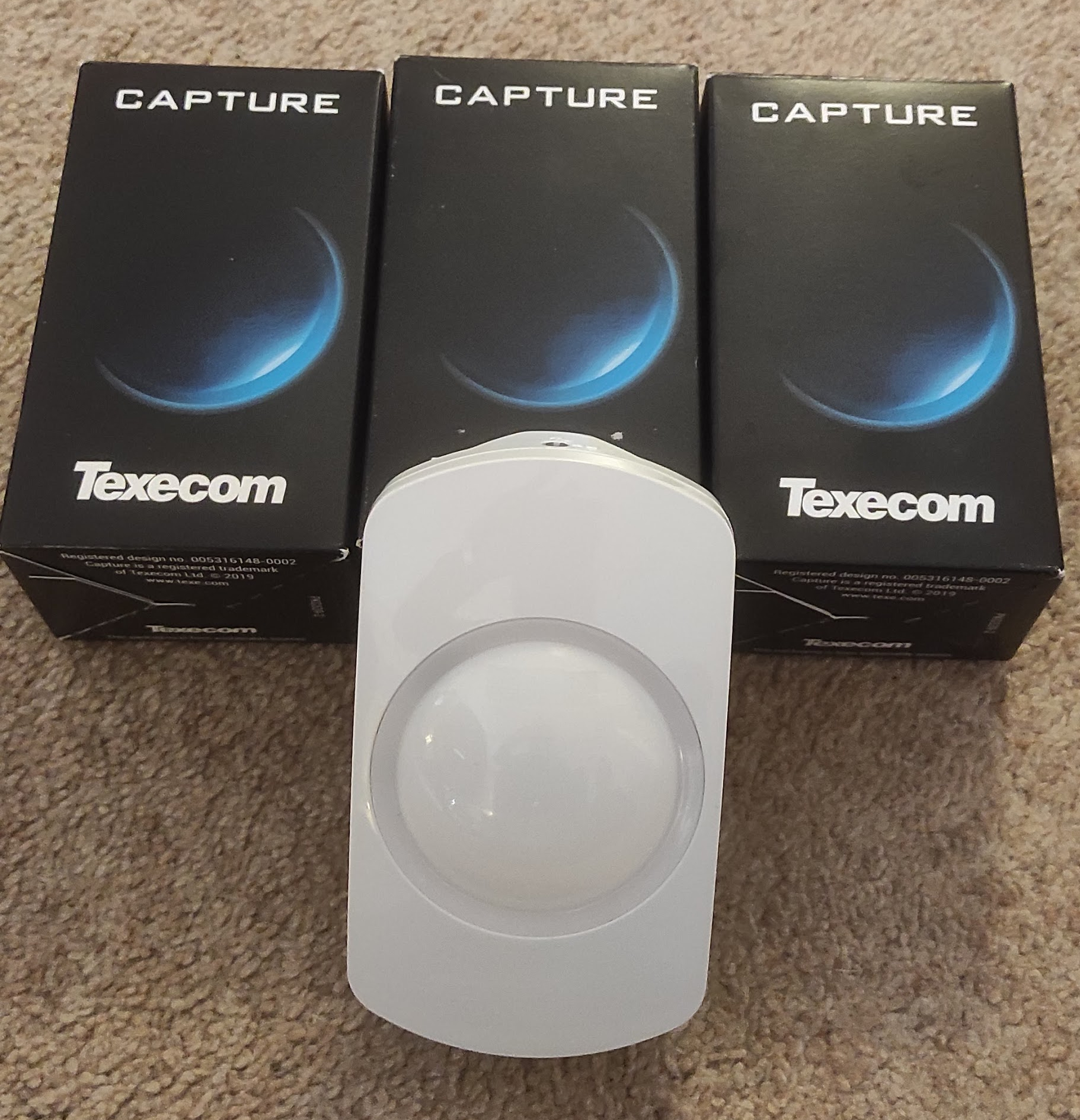
They have also very kindly sent me some to have a look at:
These are the Ricochet (wireless) types, although they have also brought out wired equivalents. They have clearly tried hard to rethink the design and make it as simple and consistent as possible. There are quite a few nice touches – the electronics are all in the front part, so when fitting to the wall you’ve only got the actual plate to deal with. Also they are all switchable between ‘pet tolerant’ and normal which is very handy. I’ve had to replace quite a few sensors since recently getting a cat, and in fact this was the main reason for my wanting to replace the sensors.
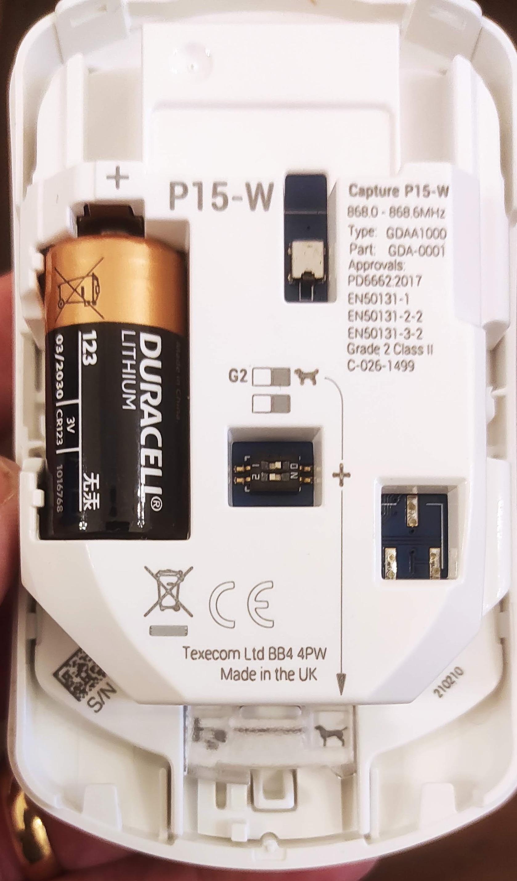
The design of things like this is really a matter of taste although personally I like this and it’s nice to see someone trying to do something a little bit different. There is an LED but it is inside the circular section and they aren’t used in the Ricochet devices except for when you first set them up.
The dip switch in the middle is used to select ‘pet mode’, in conjunction with a plastic shutter at the bottom which also needs adjusting (indicated by the arrow).
Then it’s simply a matter of learning it to the Ricochet system. There are a couple of ways of doing this and I’ve covered this before. This time, I used the ‘Learn Ricochet’ menu on the panel with the battery out, and then connecting the battery when prompted by the panel. It automatically sets up a zone with the appropriate profile (‘Guard’).
Overall I think these sensors are really nice. They are very simple to install, it’s great to have the optional pet mode and they look a bit different from the norm.
I’ve written at some length about my use of MAX thermostats and most recently the sad news that the product line has been entirely canned. This has immediately set up a supply problem and I had great difficulty in getting hold of another when I added a radiator and I actually had to get one shipped in from a contact in Germany, When it arrived I tested in briefly and it powered up so put it on a shelf until I got round to fitting it.
Today was the day, and I was extremely dismayed to find that when I tried to install it, it immediately failed with an F1 error. The motor would run for a fraction of a second before stopping. The manual states that this is error relates to the motor running slowly.
I have stripped these down before, and the gearbox is a fairly simple mechanism but still has quite a few plastic cogs. To open the casing you need a small Torx T5 screwdriver with quite a long reach to get the four main screws out (under the battery cover). It’s quite awkward inside with the wires from the battery box and the motor, although you can lift the motor and gearbox out.
I had a look at the gears and they did move although it does take quite a lot of effort. However looking closely at it I could see some damage to a different set of wires that go from the board to the motor assembly. Inside there gearbox one of the cogs has four reflective dots on it and there is a light sensor in the housing. This is used to measure the speed of the motor, and it struck me that the most likely reason for the error was that it wasn’t reading anything from this sensor and thought the motor wasn’t moving at all.
As an aside, I also remove the PCB from the housing with the screen and the buttons because I thought it would make things easier – but my advice is, don’t do this! The screen is not fixed in and there is a sandwich of plastic and other bits which took me ages to get back together again.
The wires that were damages are part of a 3-way ribbon cable which connects pads on the board to the motor housing. This cable is very stiff and only just long enough and I couldn’t strip enough insulation off the broken end to reattach it. So I ended up removing the cable entirely and replacing it with new wires. The pads on both ends are very small and tricky to solder on to, and I struggled to clean then off. I also found that the unit wouldn’t boot if there was a short.
I used some solid cores out of an old Cat5 cable which were thin enough and easy to solder. Rather to my surprise I was finally able to do so and put it all back together again, and then it worked perfectly. So it’s definitely worth persevering with these, they aren’t hard to repair but the internal wiring is definitely a weak point.
I’ve always liked music and music tech, although I’m not really much of a musician myself. I’ve written before about repairing an old Casio keyboard rescued from a skip. I’ve started looking around recently at old, unregarded and (importantly!) cheap synths to play with. The classic 1980s ones like the Yamaha DX range are now really quite expensive (£500 or so for a decent one) making me regret not looking at this before given that a few years ago you could have got one for next to nothing. However trawling ebay I found someone locally selling a Kawai K1 untested reasonably cheaply so I bought it.
I’d not really heard of this one but it appears that it was quite popular back in the day and they sold a lot of them. They seem to have been in the doldrums for years but there does seem to be some interest again. There are a few interesting websites with more information:
The one I got was in a pretty sorry state when I got (and not _quite_ as described by the seller either!)
There is some damage to the casing on the front at the right and the rightmost keys are slightly damaged. It’s a bit shabby all over with some dirty keys and needs a good clean. It came without a power supply although it’s a standard barrel connector and a 12V power supply (although ‘centre negative polarity).
I was pleased to find that it powered up without an issue, although on trying to play there were quite a few issues. Some of the piano keys didn’t work, none of the control buttons worked and the joystick didn’t seem to do anything. I had a strong suspicion that the internal battery had failed too.
So first job was to open it up and have a good look. The Kawai blog above has good advice on doing this, basically a matter of removing all the screws on the base of which there are several different kinds. There is a good account of it here:
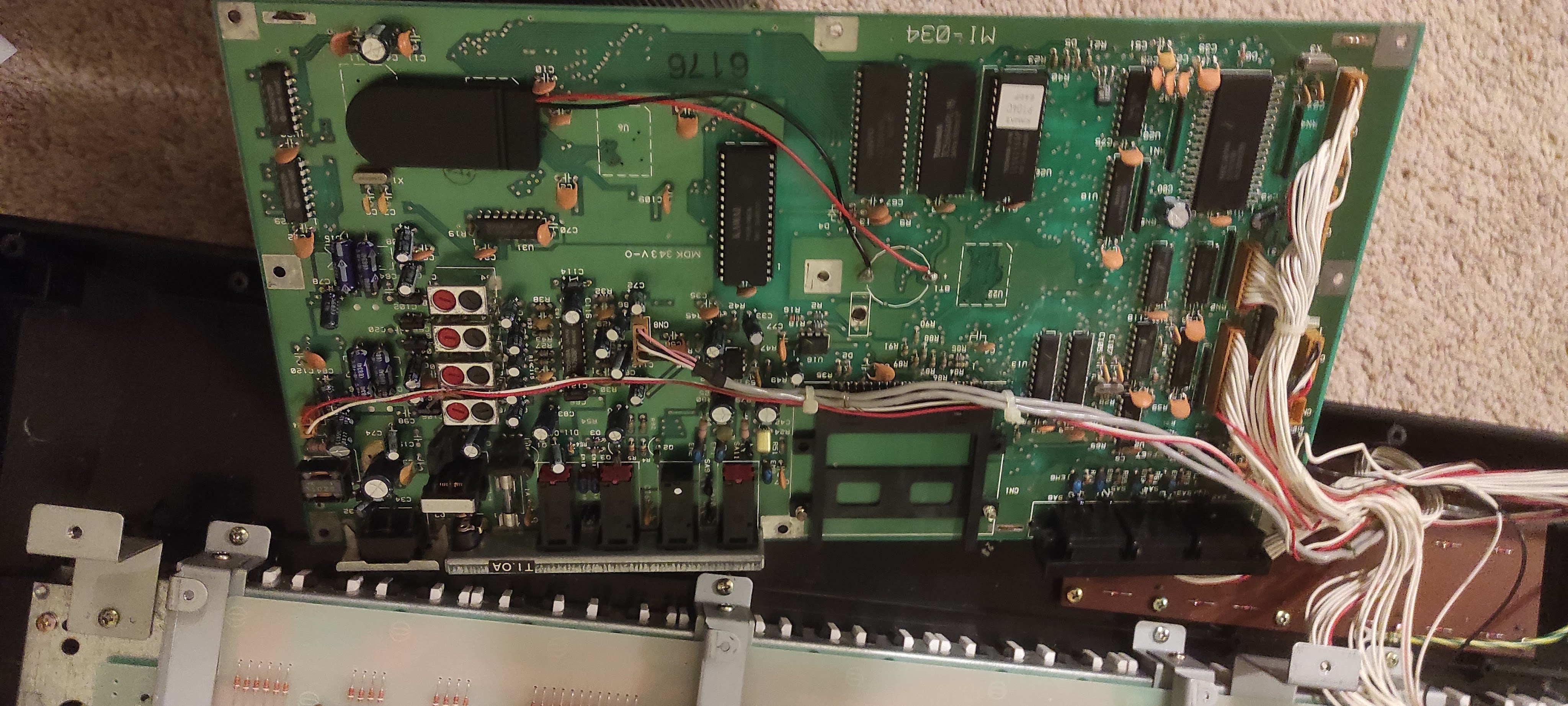
Once I got inside there were a few broken bits of casing rattling around but in general not too much obvious damage:
The main board has a copper sheet on the bottom, but you can get to the top of the board by unbolting the board and carefully flipping it over:
There’s nothing obviously wrong here other than a badly bodged backup battery install. It looks like someone has torn the straps off the old battery and put a new one in with sticky tape, but it’s not really worked. I could replace this with a proper tagged battery, but these are a bit of a fiddle and so instead I thought I’d use a battery holder. There seem to be quite a few of these out there now, and I found a lot of these out there:
They are very cheaply made, but let you install one or two CR2032 batteries in a case and solder the flying leads to the board. This should make it much easier to replace the battery in future should this ever be needed. So I cut down the old tags and soldered the wires on, fortunately the positive terminal was marked on the board. I stuck the holder to a convenient space on the board with some self-adhesive tape:
The next problem is the unresponsive piano keys and control buttons. For both of these it was simply a case of stripping everything down. These keys work by a rubber mat which pushes down on some PCB based contacts. I was able to unscrew the button board and pull the mat off, and clean the contacts up. It was the same approach for the piano keys, and the details are in the post linked to above. There was nothing obviously wrong with any of the contacts but there was a fair bit of fluff which I cleaned up. I had read on the internet somewhere that people had trouble with the copper sheet under the PCB so I took that off too although it didn’t make any different. However it gave me a chance to have a good look at the underside of the PCB which again looked fine.
There was also some damage to the top ‘C’ key and a stabilising post had snapped off. Unfortunately I broke this further trying to get it out and whilst the key still works it is a bit loose and gets stuck. However I can’t think I’ll have much occasion to use that particular key anyway.
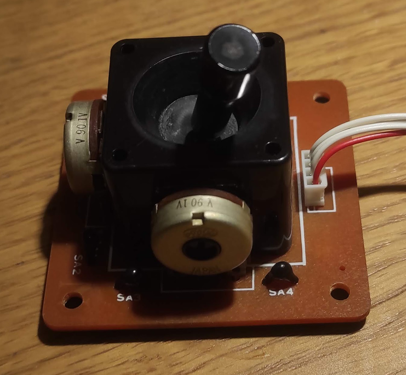
The final thing to look at it is the joystick. I’m not entirely sure how it is meant to work but it seems to be working reasonably well in the Y axis but not in the X axis. These joysticks are actually fairly simple devices with two potentiometers:
From a few measurements they seem to be fairly standard linear potentiometers tracking from 0 to 4.2k. There doesn’t seem to a big problem with them from measuring with the meter, and similarly the cabling etc also seems fine. However I’ve sprayed a liberal amount of switch cleaner on it, the connectors at the other end and the socket on the main board. After leaving it overnight to let the cleaner soak in I gave it a good wiggle around in both axes before refitting it.
Then it was simply a question of putting it all back together again and testing it. Somewhat to my surprise… basically everything worked! The keys all work, the control buttons work (although they do need firm pressure) and the joystick also works smoothly in both axes. So it’s rather a shame about the physical damage, it would be great to find a new casing from somewhere although that’s a bit of a long shot.
The backup battery is also working correctly, so the next thing to do is reload all the stock factory patches and get some more interesting sounds out of it so that’s for part 2.
I’m having a lot of building work done at the moment, and I’ve always tried where I can to do little things to improve the tech in the house although usually in a ‘stealth’ or reversible way. So this time I’ve been able to sneak in a bit of extra wiring to make my Fibaro Z-Wave modules work better with the 3-way light switches (that’s a story for another day) and also I’ve installed some decent commercial wifi access points in the new ceilings.
Perhaps predictably one area of the house I’ve generally called my own is the cupboard under the stairs, although it’s generally been a bit of a mess with dodgy walls and ceilings and a lot of dust. This is where the Texecom alarm is, plus all my Internet wiring. Over the years I’ve added some refinements, such as some Cat 5 network cabling to another room (although I’ve mostly not used this) but it’s never been tidied up. So my ‘infrastructure’ looked a right old mess with wires everywhere, something like this:
So quite a mess although some of that stuff is storage (eg the rack units aren’t doing anything) but you can see the network cabling and some of the stuff on the shelf including the network switch and cube server.
The cupboard is built under a flight of stairs, and this means that it is triangular in shape and rises actually quite high up with a lot of space above your head. I was trying to think of the best way of mounting everything, started off with the wall but then it struck that the triangular panel immediately behind the door would allow me to get almost everything off the floor and run the cables in a manner which could be tidy but also leave everything acccessible.
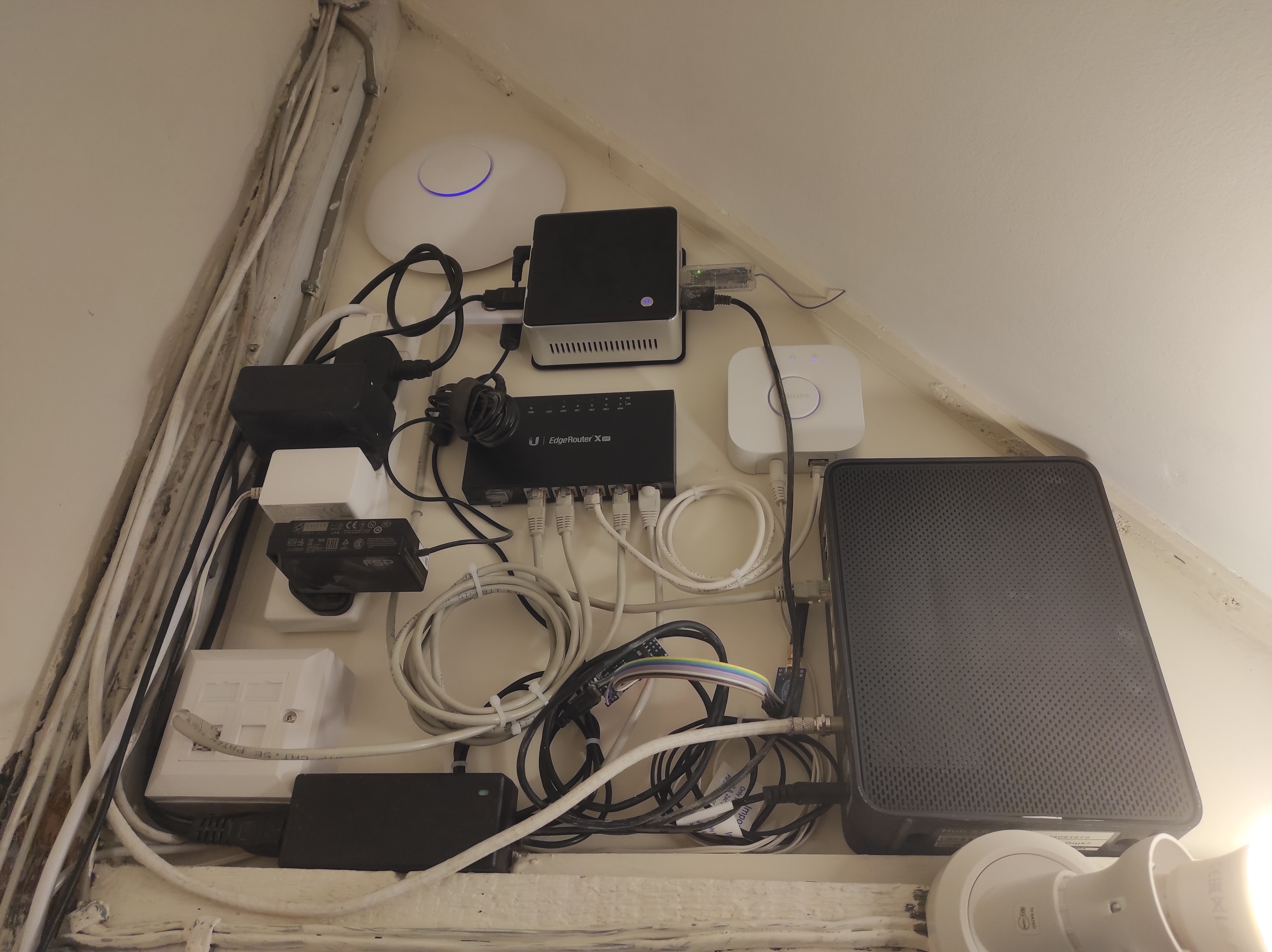
So the result looks like this:
There’s a few things I’m not 100% happy about – mostly the amount of excess cabling I’ve had to coil up – but in general I’m pretty pleased. Going anticlockwise from the right, we have the cable modem on the far right, then the Hue bridge (white box), then an Intel NUC (on it’s VESA mounting plate) which replaces the HP cube server. This has a few USB dongles plugged in including a Z-Wave interface, the CUL device and links to the Texecom alarm and a Signalduino. At the top is a Unifi access point, and the in the middle is a Ubiquiti EdgeRouter X which is the heart of the system. There is a standard 4-way power strip mounted vertically and then bottom left is a double network socket.
Most of this stuff had slots and holes on the back to allow fairly easy wall mounting. The only exception is the cable box, but I was able to drill a small hole in the top and attach a mounting block which is then screwed to the wall. Another big advantage of this wall is that is actually a wooden partition with an MDF board glued to the back which made it very easy to screw everything in.
To make it perfect I’d want to shorten all the cables so that they were just long enough, but this isn’t easy without a lot of effort and also I wouldn’t want to butcher the moulded power supplies etc. There is a little bit I can do with the USB cables and the Signalduino needs mounting on a PCB rather than using a lot of wires as at present.
As a quick aside I have really liked using the Ubiqiti kit. It is a significant cut above the standard domestic brands (Asus / D-Link etc) in quality and the software is very slick and powerful. The performance is dramatically better too. I have two of these access points in the house and they cover it with ease and with high speeds. So I’d thoroughly recommend this, it’s not even very expensive (the router was about £60).
So all in all I’m very happy… now on to the next job.
It’s been a long time since I’ve written about my adventures with alarm systems. I still have a box of Texecom goodies to go through, although other life’s priorities have got in the way unfortunately… but I will return to it.
However I noticed something interesting today in that Texecom have launched a new range of sensors called ‘Capture’:
This is a great bit of marketing, but also looking at the website there seems to be some really interesting tech going on here. For example pet detection comes as standard and there is a choice of ‘pet detection’ algorithms. There is also a range of form factors including ceiling mounts. Now whilst I am far from being a veteran of the security industry I’ve never seen anything quite like this before, so full marks to Texecom for this.
I’m going to try and get on in somehow and have a proper look at it. I’ve been doing some work on my system too, including installing a flush mounted keypad so will post on that soon.
I have written at quite some length on here about my use of MAX equipment for running my heating system. It has worked extremely well and I have been very happy with the excellent quality of the kit and the low prices.
I found I needed an extra thermostat, but on looking around the usual sources they were nowhere to be found. A bit more digging and my worst fears were realised – the range has now been discontinued by the manufacturer (ELV). The UK has always been a minor market for this stuff with Germany and other European countries seeming far more interested. The press release which puts the final nail in the coffin is here:
Whilst they are dressing it all up as a good news story, for me at least it feels like bad news. They have always had a range of different product lines, and the HomeMatic line have always been nice but much more expensive, and also more complicated to control if you step outside their ecosystem. I never made any use of the cloud offering so that’s not an issue to me.
I don’t see HomeMatic IP as a viable solution really partly because of the cost, but also because it will be much more difficult to incorporate into my control system. Fortunately for me I don’t need much more, probably one will be enough, but it is still a bit sad that the options are becoming more limited. If I was starting again now I’m not really sure what I’d do. There are some options out there but I don’t think any are easy.
ELV are offering a like-for-like exchange of MAX for HomeMatic IP thermostats… but sadly the Ts&Cs only apply to a number of European countries which does not include the UK. I’m not really surprised by this, they never really seem to have engaged with the UK as a market and I tended to buy mine from European retailers like Conrad or even direct from ELV.
It does mean that I am now going to try and hoard as many as I can find, there are one or two job lots that go on eBay but not very often. So if you have any of these lying around… please let me know! I’d also be very interested to hear if anyone has had success with other similar systems especially when coupled with FHEM or some other computer controlled system. Fibaro are doing some very expensive Z-Wave heads:
All the other options are similarly expensive and not as easy to integrate.
I’m not planning to change anything and hopefully my existing installation will continue to work fine for a long time to come. However it does leave a real gap in the market, and in the UK at least I am not optimistic about it being filed.
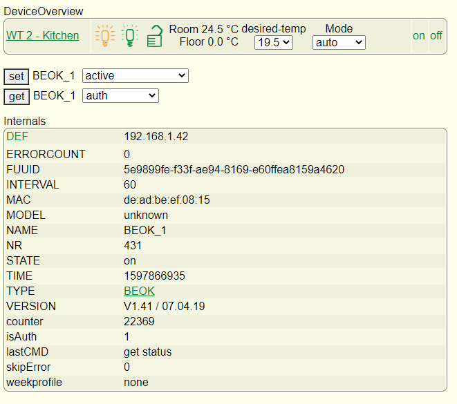
Having installed the new thermostat as detailed in the last post it is working fine as a standalone device, but the configuration in FHEM is needed to get the value out.
I’m always impressed by the amount of information you can get out of simple devices and this is no exception:
There are also loads of various readings you can get out as well, including a regular temperature reading which is great for monitoring:
You can also set almost any of the parameters, including the weekly profile and various other things.
What I needed to find was a way of stopping the heating from running when the back door is open. When the cat goes out the air temperature in the kitchen drops rapidly and it is pointless to run the heating until she comes back in.
There are a number of possibles, one of the most obvious is a ‘frost protection’ mode which many thermostats have and although there is a setting for this it’s not mentioned in the manual and doesn’t actually seem to do anything. I could actually have simply switched the thermostat off completely (which I tested and worked well) although this felt a bit over the top and would stop the temperature monitoring.
I settled on switching between manual and automatic modes, with the manual setpoint set fairly low (around 15 degrees). So when the door is open the setpoint drops and the heating switches off. You can see evidence of this in the green line on the graph above.
This is done in FHEM using notify events and some simple commands. It is simply a matter of ‘set BEOK_1 mode auto’ or ‘set BEOK_1 mode manual’ in response the event. This is done simply in FHEM using ‘notify’ events, one for the door opening another for the door closing:
To define this in FHEM I used the following:
define HeatingBackDoorClosed notify TexecomDigi4:reading:.off set BEOK_1 mode auto
‘TexecomDigi4’ refers to the digital output, which is on when the door is open and off when closed. So whenever the door is closed, the trigger of the Digi4 to ‘off’ creates an event which sets the thermostat back to automatic mode. A similar one is in place to handle the door opening events.
I was pleased to find that this worked first time, and even with repeated and rapid opening and closing it doesn’t go out of sync. It has been far too warm lately for the heating to come on anyway and the cat has enjoyed long days in the garden but this is likely to change as we get into the Autumn.
So now I need to think of a few more use cases… and there are a lot of Texecom goodies to go at still.
In a previous entry I talked about building a hardware interface to the Texecom panel with a few ideas in mind, but initially triggered by wanting to avoid heating the kitchen when the cat is out:
Less of a problem in the summer of course, but also a good time to play around with heating controls. I am still using FHEM as my central control system, basically because I have yet to find anything better. It does perhaps look a bit old fashioned now but it is very functional and still has a broad range of compatibility.
My kitchen underfloor heating is controlled by a solenoid valve, which when energised opens the flow to the heating pipes and calls for heat from the boiler. The original control was a Heatmiser Neo which is a nice system and ‘automatable’ – but only if you have the matching hub. In any case it doesn’t work with FHEM and I’m not sure how open it is.
My requirement was for a normal wall thermostat / programmer which could also be controlled remotely by FHEM and which looked the part. As it turned out, this was not easy to find or at least not without spending a lot of money. There are quite a few ‘wifi controlled’ thermostats out there which use some kind of an app, but most of them are standalone and not supported by anything much.
After a lot of digging around I came up with the BEOK BOT-313. This is a fairly typical low-cost Chinese import but someone has decoded the protocol and it is supported natively by FHEM:
Getting hold of one proved a little more complicated than I’d hoped. It turns out there are several different versions of this which are designed to work with a number of different heating types. I originally got one from Amazon but it turned out to be a version for use with an electric heater, and did not provide the simple relay that I needed. Instead it simply provided a Live and Neutral output. So whilst I could probably have hacked things together I eventually took a deep breath and ordered the correct one direct from China on Aliexpress. There are various choices but I got the 240v wired in version.
There is a lot of debate on the FHEM forums about different software versions on these devices, which are also sold under a variety of brands (Fluoreon is one but there are various others). However the safest thing seems to be to buy this particular one.
I have bought stuff from China before and so I knew what to expect but I was pleasantly surprised by the quick delivery, it did take a few weeks but that’s not bad given the circumstances. It was cheap too!
Installing it was fairly easy, it’s just a matter of connecting up the mains supply and the boiler terminals. You can use it as a standalone unit, but the value clearly lies in getting it on the network. Unfortunately this is not easy as you have to use the BOK app which is pretty ropey. The other thing is that it only works with 2.4GHz Wifi and it won’t connect if you have a 5GHz network on the same SSID, so I had to temporarily disable the 5GHz before it would pair. Once this is done you can switch the 5GHz back on again and it works fine.
So with the hardware in it’s a matter of configuring it in FHEM… so more in Part 2!
I’ve had a passing interest retro gaming for years, although it’s more about the tech than about actually playing the games (which I’m really not very good at). I have got a small collection of odds and ends, and one thing which I got more recently was a Gameboy Advance SP Zelda edition, rather like this one:
One of the nice things about these is that the play original Gameboy carts, and back in the 1980s there was nothing I wanted more than one of these. I fell in love with the accessibility and sheer playability of the games in (what seemed like) a small and compact package. I spent a lot of time with them after borrowing them from friends but never had my own.
I did start looking out in second hand shops for cartridges though, just to see what I could get my hands on. I found a couple of interesting ones, but the best was a Pokemon Silver cart:
It was just the bare cartridge and it worked fine, although it was clear straight away that there was a problem. These cartridges use an early form of ‘save game’ technology, done very simply by using battery backed RAM. At the time I remember this seemed like magic as the cartridges were identical to normal ones and there was no sign of the battery externally. However, after 20 or more years these batteries have unsurprisingly run out of life, and so whilst the game worked fine it didn’t save anything and you had to start again each time. Sometimes these old batteries leak and damage the actual electronics, I previously bought a Pokemon Red for which that had happened and the game simply wouldn’t start.
Fortunately as this is a common problem it was easy enough to find what I needed for repair. The cartridges are held together with a single ‘security’ screw which needs a special screwdriver, and these are easy to find on eBay etc:
They often come in sets with other sizes for different Nintendo products, eg SNES cartridges. Make sure you get one for the cartridge, the actual consoles use another type of special screw (a ‘triwing’) for which you can also buy screwdrivers. I have some of them too… another story!
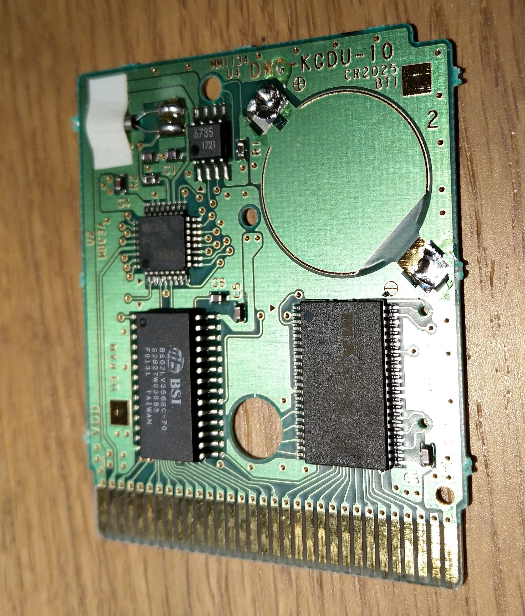
The other thing to do is make sure you have the right battery. There are at least two types (earlier games use a CR1616, later ones often the more common CR2025), and the easiest way to check is to open it up and have a look:
Printed on the board is the battery type (CR2025) and the date code shows it was made in January 2000 so shortly after the game was released. The battery is soldered in rather than socketed, so you do need to find a replacement with tags or else hack in a normal one. There are various suppliers on eBay and others who carry these so they are easy and cheap to find.
I took the opportunity to take the old battery off an clean the board up a bit. It’s in pretty good condition given its age:
Installing the new battery was pretty easy too, just a couple of blobs of solder, but as always make sure you get the polarity correct (in this case negative is the lower right and positive the upper left terminal). The replacement battery I had the contacts in a different place, so it looks different but the polarity is correct:
Then it’s just a matter of putting it back together and testing – which worked fine – so now it’s a question of actually getting on with the game!
In an earlier post I talked about work done repairing a Playstation 3 controller, but a couple of years down the line and an upgrade later I’m in a similar position with a PS4 controller aka a Dualshock 4.
This time the problem is with one of the small joysticks / analogue controllers. One of them was frequently getting stuck or becoming unresponsive. Unsurprisingly this is a common problem, and there is lots of information out there on this.
The sticks are made up of a mechanical centre which handles the movement and the push button, and two carbon ‘wipers’ which track the two axes of movement. Dismantling the controller is fairly easy (just a matter of removing the screws and teasing it apart) and then you are left with the main board:
The internals of a DS4 controller
You can see on the right the complete stick. On the left, you can see the two green sections (which contain the wipers) have been popped off the main body and bent back on their pins revealing the wipers (white). It seems you can bend these back and forth a good few times without them breaking but you do need to be careful.
I was able to buy complete replacement stick assemblies for a few pounds off eBay. The first time I did it I simply removed the white bodies and cleaned out the inside with switch cleaner before replacing with new ones. This worked for a while, but then I hit problems again.
This time I decided to replace the green units completely. This should have been easy – simply a matter of desoldering three joints and replacing with a new one. However for some reason this proved extremely difficult. I just couldn’t get the solder to melt cleanly, and the pins eventually broke off in the holes and it proved a right pain to suck what was left out and clean up the holes. Somehow or other I eventually managed it and was able to solder in a new one, but it was so awkward I left the other one in place. By good fortune the one I started with was the one with the fault.
After getting it back together again everything seemed to work except the controller would not charge. I went back over the board and scraped off a few stray blobs of solder and after that it seemed to work correctly again.
So whilst these controllers are repairable it’s a fiddly job. You probably need a professional solder sucker to do it, I was using a good iron but only a cheap manual spring loaded sucker which wasn’t up to it.
I might have been unlucky… but at least now I have a working controller again! They remain really quite expensive to buy.