Something completely different…

I am taking a slight detour here from my usual stuff to talk about something a bit different. I am going to return to Texecom and electronics but just lately I have been preoccupied with other things so I thought I’d write about them as well.

I am not really a petrolhead as such, but I do like interesting or unusual cars and I do (as you have no doubt gathered) like tinkering around fixing things where I can. Some cars I’ve had have been interesting (Saab 9-5 Aero, Saab 900, Rover 800 Vitesse) and some… less so (Rover Metro, VW Polo, Ford Focus). I have had some success over the years with various car related jobs although they have generally been electrical rather than mechanical, such as retrofitting factory Bluetooth / USB interfaces (Ford S-Max) and similar job for adding remote central locking (VW Polo).

I found myself in need of a new project, and this time I fancied something a bit sportier, and also wanted a low initial cost. Breaking all the rules, and rather impulsively, I came home with this:

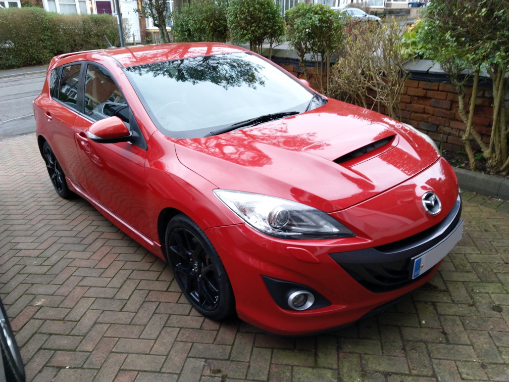
…or rather when I say I came home with it, I bought it as a non-runner with very little knowledge of what was actually wrong with it. I can’t exactly recommend this approach, very risky, although so long as you don’t spend too much it’s OK. I have seen quite a few other cars older than this sold as non-runners for more than I paid so I think I’m ok for now. Still you have to consider the possibility of it turning out badly.

In case you don’t recognise it (I wouldn’t have) it is a Mazda 3 MPS Mk2 from 2009. These are relatively rare and little known cars (less than 1000 of them left now) in a similar class to Golf GTIs and Focus STs. It has a 260BHP 2.3l turbo engine, and a fair amount of attitude as you can see from the picture.

I bought it very much as a project – in the full knowledge that it will need money and effort spending on it. However I didn’t pay much for it and I reckon that even with a fair amount of money spent I won’t have lost any money. When I first saw it it was in a sorry state, mouldy inside with a lot of water, completely dead and according to the previous owner wouldn’t start after running out of fuel. I’m not sure this was the whole story though.The local garage had a mess with it, and after draining out a lot of oil and replacing plugs and filters it started and ran, albeit with a lot of blue smoke and misfire errors from the on board diagnostics.

So first job is to get the mechanicals sorted out. It is currently with a local turbo specialist as I think the turbo needs replacing (drinking oil and producing a lot of smoke) and I understand that the K04 turbo in these cars is prone to failure. My analysis is that the previous owner found it was drinking oil and kept pouring more in, overdid it and then gunged up the plugs leading to it not starting at all.

I am hoping that doing something about the turbo will address the major issues, and then I can turn to the smaller ones.

So far these are:

i) Lots of water in the boot

ii) Some damaged loose / trim inside

iii) GPS / sat nav not working

iv) Bluetooth not working properly either (only pairs with phone and not media audio)

So I will write some updates as we go and hopefully as I tick things off.

I might have bitten off more than I can chew here… but it’s a bit of an adventure too. Also I hope I can keep one more of these on the road, you don’t see many around and I think they have real character.

LCDLP-W Ricochet Keypad review

This is the first of a series of short reviews of the various bits of Texecom kit which I have now have, as listed in a previous video. These are my entirely non-expert opinion but hopefully will be of interest if anyone is thinking of getting any of these in.

This is a Ricochet (ie wireless and battery powered) version of the LCDLP keypad. Texecom do a range of keypads, of which this is the highest spec (being the ‘Premier Elite’ range). The cheaper ones have a smaller display (‘Premier’) or no display at all (‘Veritas) and do look rather old fashioned now. I’m not sure whether all keypads are compatible with all panels either.

There are also two types of Premier Elite keypad, one a surface mount (the LCDLP-W is also one of these) and the other a flush mounted one (without the keypad cover for some reason) which needs a back box sinking into the plaster. These come in various different finishes – brass, brushed metal etc. I think these look very nice, and when we get our hall redone I’m going to have one of these installed instead.

The other thing to note is the ‘P’ in the model number means that it also accepts proximity tags. You can get some of the models with and without tag reading capability. I’ve got some tags to look at and I’ll cover them in another post.

So as above, what I’m looking at now is a Ricochet version of the surface mount keypad. To look at it is exactly the same from the front, although a bit thicker and heavier because it has batteries in it. Here is a short video showing you round:

Learning the keypad to the panel is really very straightforward. The main thing to watch out for is to set the keypad address using DIP switches on the rear. If you are only using one (or if this is the primary keypad) you can leave it set as it is (which is address 1). However as I already have a main keypad I set the switches to address 2.

Once is done, you put the panel into engineering mode and press the ‘Omit’ key, then when prompted to ‘Learn Ricochet’ press ‘Yes’ (or the tick). There are then a few prompts to work through but following that the keypad syncs up and then behaves exactly like a wired one.

So the positives are that it is dead easy to set up, no wires are required and it can be mounted pretty much anywhere. There are a few negatives though – the display is off most of the time, and comes to life when you press a key. This is undoubtedly for power saving, and I think you can disable this but if you do it will compromise the battery life significantly. The other thing is that the LCD display is just not as good as the one in the normal keypad, at least to my eyes. It works fine, but the viewing angles and brightness are simply not as good. I wouldn’t really have noticed this without putting the two side by side, when you do it is quite noticeable.

So overall, if you want an easy way to put an extra keypad in, this is it. I would still I think prefer a wired one for the main keypad but for a back door or garage it would be ideal, or even if you just didn’t want to run any wires at all. It’s entirely possible to build a whole system out of Ricochet which is quite a tempting idea if you don’t already have wires in place.

I’ve now installed this by my outer front door, which previously wasn’t connected to the alarm and there are no wires in place. I combined this with one of the contact sensors (see previous post) to effectively add an extra zone which now makes much more sense from a security point of view.

Here is a quick video with a summary of my thoughts and a demo:

Philips Hue Stealth Installation

I’ve been experimenting with different light control systems for years, as I’ve talked about on here before. This has mostly been Z-Wave using Fibaro devices. These are great bits of tech, but they do have drawbacks. They are quite expensive (about £50 each) and the dimmer versions (which are needed for 2-wire installations, common in the UK and in my house) often need an additional ‘bypass’ if you are using with LED bulbs which are low wattage. This is extra expense and quite fiddly to install. However they are extremely clever, have loads of settings and options and are completely ‘stealth’ in that they work fine with normal light switches.

I’ve become increasingly interested in the Philips Hue system largely because of cost and ease of use. The bulbs are increasingly cheap especially those made by 3rd party manufacturers. For example the range of Innr bulbs:

These can be had for less than £10 each on Amazon for the plain white ones, and even the genuine Philips ones are down to about £13 now. If your room only has one or two bulbs, it feels a lot cheaper and easier to use these rather than a Fibaro dimmer and bypass plus dimmable LED bulbs which are not cheap in themselves.

You do need to have a Hue hub to get started which are not cheap, but once you have one (I bought mine as part of a starter back in a sale a couple of years ago) you can add as many bulbs as you like (although there must be an upper limit I’ve not hit it yet). The hub is well supported by FHEM so easily integrates with my other ‘smart home’ devices

So far all good, but there is one major flaw which is the switching. I like to keep all my home automation kit as ‘stealthy’ as possible, preserving normal ‘interfaces’ (ie lightswitches) or making things completely automatic. Hue doesn’t allow for this at all, and because the bulbs obviously only function when switched on at the wall, if people use the normal light switches and turn the bulbs off then you can’t turn them on again!

What they do supply are a couple of designs of battery powered remote control / wall switches. One is the ‘Tap’ :

This one has three buttons so is quite flexible, but it’s a funny shape and I don’t really like the look of it. It’s also really expensive (£50) and hard to see how to make it stealthy.

The other option is the more straightforward ‘Dimmer Switch’:

This is rather more conventional looking, and a lot cheaper (RRP of about £17). The design is quite clever, in that the buttons are held to the backplate by a magnet which means you can detach it easily to use as a remote control and it also help with fitting.

What is frustrating is that Philips don’t seem to acknowledge the switching issue, and the instructions suggest fixing the switch to the wall with sticky tape or screws. There is no mention of what to do with the existing switch, and havoc would ensue at our house if I tried to tell people not to use the ‘proper’ switch but this instead.

When I actually got the switch in and looked at it, it struck me for the first time that this had been thought of… but only for the US market. The backplate and screw fittings are clearly intended for the longer, thinner US style light switches (which have always looked odd to me):

The intention clearly is that you should remove the switch entirely, hard wire the connectors together and replace it with the Hue switch so it’s obvious which to use and it looks fine with the decor. It also removes the risk of anyone turning the light off rendering it no use for remote control.

It is very irritating that Philips haven’t produced a UK version, you feel it would be quite easy as all that would be needed is a different shaped backplate. The US ones are much narrower than the UK ones, so you can’t just fix it over anyway because it will leave a gap either side and look a right mess.

Clearly I’m not the only person to have this idea, and there are a lot of solutions out there although I’m not impressed with most of them. The most common seems to be 3D printing a frame which fits over the whole existing switch with the Hue on top. The result is a huge box on the wall, and the quality of the finish doesn’t look good. It feels like a bad hack to me, and the results I’ve seen are not impressive:

However, after a bit of digging around I have found some alternatives, because what I really want is a plate which converts from a US switch to a UK one. There are a couple of these out there, and the best one I have found so far is from Etsy:

The supplier (DFXHome) seems pretty well regarded and does a range of similar products. It also comes supplied with a connector to hard wire the switch wires. This one is specifically designed for the Hue switch and the whole plate is designed to snap in and there is a sloping profile around. The advantage of this is that it keeps the whole of the Philips supplied unit which looks much nicer. The only problem is that like all 3D printed items the finish is a bit grainy.

I’ve got one of these in now and it’s installed, and I’m really quite happy with the result. The family have got used to pressing the buttons and I’ve been able to make good use of the automation aspects, using FHEM to trigger some LED strip lights as well the main light (I’ll cover this in another post). This is how it looks, there are a few rough edges but the overall effect is good. I suspect you could sand it smooth with some fine sandpaper and overpaint it although I’ve not actually tried this.

Given how successful Hue has been I really hope that Philips will produce a UK version of the back plate… but until they do this approach is the best available and I’d recommend this product.

I’m probably not going to spend much more on Z-Wave now so I think I’ll be installing a few more of these!

Interfacing and configuration

Having installed the interface board there are two stages to configuration. The first is to get the panel itself to trigger the outputs and the second is to interpret them in FHEM and trigger some actions.

The outputs in Wintex are located in a section labelled (helpfully) ‘Outputs’ in the programming menu:

There are a lot of different ways of configuring outputs as you can see. I was previously using the ‘Panel Outputs’ at the top, with ‘System Fully Armed’ being the trigger to throttle down the heating. However, I’m now interested in the eight ‘Digi Outputs’ listed underneath.

For each output there is a bewildering array of possible options – there are eight groups (system, area, zone etc) and each group has numerous other options. For example, the ‘user’ group allows triggering of output on a specific code. The level of detail is really impressive and pretty much anything you can think of is catered for.

My needs are quite simple, I want to trigger an output for system armed (for the heating), and for activation of the PIRs and back door contacts. This is done by selecting the ‘Zone’ group and setting the correct zone number.

The other thing to set is the ‘output function’ which dictates the behaviour. I want to read the status regardless of whether the alarm is armed so I have used ‘Mimic’. There are other ‘attributes’ you can set, I could have used ‘inverted’ which would have pulled the output high on trigger, but I can accomplish the same thing in the software at the other end so I left it alone. I need to think about what else I could use these outputs for, but for the moment I have assigned them to various of the zones around the house including the all-important back door to accommodate the cat.

Once the programming was sent to the panel, I was pleased to see the LEDs displaying what I expected – those corresponding to the PIRs went out whenever it was triggered.

I’m not going to go into great detail on the FHEM configuration, which is a little fiddly (but if you are interested please contact me and I’ll try to help). The Arduino has the ‘Firmata‘ sketch loaded and this is attached in FHEM as a USB device:

The various pins are made available for use (in my case pins 2 – 9) and you then define the pins you want to use as inputs as a separate device:

You can reference the reading of (in this case) ‘TexecomArm’ in logic which does things based on the condition. In FHEM-speak this is done using ‘notify’ events. I have used ‘notify’ events to switch on the main lights in some of the rooms when the PIR is triggered:

It looks a bit complex, but the relevant line is the ‘DEF’ at the top. The command is triggered when TexecomDigi2 (ie the 2nd Digicom output) reads as ‘on’. The event is to ‘set Hue_HUEGroup2 on’ which turns on a series of Hue lights in the room.

The only problem was that we watch films in the front room sometimes, and we turn the lights off. In that situation, you don’t want them suddenly coming back on again. Luckily, FHEM can also talk to various other devices I have including the home cinema amp (a Denon AVR-X2000). Therefore, triggering the output evaluates an ‘if’ expression, and it only triggers the lights on if the amp is off (or rather, if it is not on – ‘ne’ meaning ‘not equal to’). So if the amp is on and we turn the lights off, they stay off. If the amp is off (and therefore no-one is watching anything) the lights come on.

Although these are only small things, they really show the value of having as many data sources as possible and making things work together to really anticipate what you want. I’m really excited to see what else I can think of for this, and further expand how the panel and the rest of my devices at home work together.

Oh and concerning the cat… I now need to get a wifi thermostat for the underfloor heating that FHEM can address. I have a Heatmiser Neo at the moment but this isn’t supported, so I need either a Floureon or Beoks device instead. I’ll post further when I’ve got this working.

Texecom and FHEM interfacing

I have written a few times about my interest in home automation and in particular my use of the German ‘FHEM’ system to link it all together. One thing I have wanted to do for a long time is get the sensor data from the alarm system readable in FHEM to do useful things with, such as turning on lights when PIRs trigger. I would love to be able to do this in software, and whilst I have most of the information I need I’ve not had the time and space to sit down and tackle the job.

We have relatively recently got a cat.

However, we don’t have a cat flap and so we have to open the back door to let her out, and leave it open so she can get back in again. This causing problems with the thermostat for the underfloor heating, and so really I want to switch the UFH off when the door is open and the cat has gone out. This got me thinking about the problem again, as I have a sensor on the back door for the alarm (see earlier posts).

I have come to the conclusion that I’m not going to be able to do this in software, so I started thinking about hardware again. In a previous post I wrote about using one of the panel outputs to trigger an Arduino to throttle down the heating when the alarm was armed, and so I wondered if I could do something similar for zones or other things.

However, the Premier Elite 48 panel I have only has two ‘panel outputs’, one of which I was using. The 88 and 168 panels have more but even then only a total of 5. I thought I could just use the other one, but looking again at the manual I saw the ‘Digicom outputs’ header on the left hand side of the panel:

So here are a total of 8 outputs, and from looking at the manual and in Wintex it seemed that almost anything can be assigned to them. In the earlier post I wrote about the convenience of the ‘open collector’ nature of the panel outputs which means that the various different voltages that things run at (12V for the panel, 5V or less for the Arduino) don’t matter. The Digicom outputs on the other hand are ‘switched 0V’ which means that they are at supply voltage (ie 12V) and pulled low when activated. So these can’t be used for direct connection and some form of hardware interface is needed.

This is of course a very common issue and there is a lot that has been written about approaches to this situation. I read about various options but the simplest seems to be to use a potential divider in which two resistors are used to split the voltage and a tap is taken from the junction between them. In this case, the idea is to reduce the 12V to somewhere between 3V and 5V to feed to the Arduino. I’ll need one for each of the outputs, and it struck me it might be a good idea to have an LED as well to absorb some of the voltage and also allow for some hardware troubleshooting. To make the whole thing as neat as possible I decided to build the interface on some prototyping board and mount the Arduino in the same place.

There is loads of stuff written about how to calculate the values needed, but often it comes down to what you have to hand. I have a junk box with various components but after a bit of digging around I found some 3k3 and 2k2 resistors, and after putting an LED in series first and applying 12V I was getting about 4.2V at the junction, which seemed fine. I added a few other refinements including pin headers for connecting the Digicom and 0V lines, and I mounted the Arduino on the same board with connections in to each of the digital pins.

The result looked like this:

Not perhaps the neatest bit of soldering ever… and I have definitely learned a few things about using this type of circuit board. I used short pieces of wire to connect from the divider to the Arduino, and some wire links here made from component leads here and there. The pin headers on the left are in two sections. The LEDS are significantly underrun but they are quite visible when lit up.

The other thing to note (not easily visible above) is that the 0V line from the Arduino was connected to the 0V line coming from the panel to minimise the risk of spurious readings or other odd behaviours (otherwise the Arduino ground is via the USB to the computer, ie not common).

Final job was to install in the Premier Elite casing:

I used some short ‘Dupont’ cables to connect to the Digicom terminals, in truth these were too thin to work well so I tinned the ends with solder before connecting them to the terminals which helped make a sturdier connection.

I was very pleased to see some of the LEDs light up when connected, although it will need some configuration in Wintex to get them working as I want them to.

So the hardware is done… now on to the software!

Unboxing Texecom goodies

At long last I am able to return to an interesting box of Texecom sensors and other equipment which I first wrote about some considerable time ago.

I thought I’d start with another video, just to show you what I have got and to set the scene, and then I’m going to work through each item and write about as well as hopefully accompanying with some short videos. I’m not giving up on the blog though as I still think it’s easier to find this sort of thing when it’s written about as well as on a video.

If anyone in particularly interested in hearing about any of these items then please let me know and I’ll start with those, otherwise I’ll work through them one at a time.

I’m still quite new to the videoing business, so apologies for the limited production values, I’ll see if I can improve that too as we go along. However I was keen to get something out there as a start.

More soon!

Repairing a Siemens Washing Machine (Part 3)

In my quest to repair the motor in my Siemens washing machine I have stripped the machine down and got access to the motor but have experienced some problems in getting the new brushes in. This is for two reasons: the first is that I have not removed the motor, and the second is that the pattern parts I have bought don’t fit properly.

Most of the instruction videos out there do suggest removing the motor but I had tried without, and whilst this may at least in theory be possible I would not recommend it. There are lots of videos out there which show you how to remove the motor, such as this one:

The key insight here is to put the machine on its side, rather than (as I had done up to now) on its back. You need to remove a panel on the back of the machine, and you can then reach inside and undo two 10mm bolts. This is best done with a ratchet or normal spanner, as there isn’t much clearance between the back of the machine and the bolt head. However I did use a socket to get it going. You also need to remove the belt from the drum and the motor spindle.

Once the bolts are out, the motor is still held pretty firmly on several plastic lugs. On this picture you can see the socket on the right hand side of one of the bolts.

To get the motor out, you need to lever it off the lugs by using a big screwdriver to move it sideways and off the lugs. You need to be ready to catch the motor when it drops off, and it is heavy!

Once you have got the motor on the bench it is a good deal easier to work on the brushes. As per the last post, what you have to do is push the brush in first (ensuring the angled edge is the right way round), and then compress the spring and push it in, and then secure in with the locking tab.

I had to cut some metal off one of the tabs to make it fit properly, and even then it was difficult. On the other side, no matter what I did I just could not get the tab to fit in, whilst the original one seemed to fit fine. In desperation, I cut the tab off completely and soldered on the original one instead. This needed a lot of heat and solder, and it did make the wire rather less flexible. After a further struggle, I was finally able to get the brush with the soldered tab installed as well. On reflection I would have been better off returning them and getting some official parts but I didn’t really have the time to do this. I have had a moan at the supplier though, so we’ll see what happens next.

It was now just a case of putting everything back together again. It was very simple to reinstall the motor and wiring and bolt it into place. However, refitting the drive belt was not initally easy at all. The belt is pretty thick and stretching it over by hand was impossible (at least for my puny arms).

However, Youtube came to the rescue with this very useful video:

The winning tip here is to secure the belt to the drum pulley with a cable tie, and then turn the drum from the front of the machine by hand. This pulls the belt on to the pulley with minimum effort and worked first time!

So with everything back in place it was simply a job of switching on and testing. I had already cleared the fault codes so did not need to do this again, and much to my relief the motor immediately came to life. I can’t really say if it is any better than before, but it is definitely working and with new brushes should hopefully last another 9 years. Having had this experience I reckon I could also change the motor itself quite easily if I had to.

So a longer set of posts than usual, and although an apparently simple task I learned a lot. If you are attempting this these are my top tips:

  • Use official parts (even though they are more expensive)
  • Remove the motor before doing anything else
  • Check carefully the orientation of the brushes before replacing them

Overall though a very satisfying result, and overcoming the struggles almost (but not quite) makes it worth having had the problem in the first place!

Repairing a Siemens Washing Machine (Part 2)

In the previous post I went into the background about diagnosing the fault on my washing machine, which has come down to some kind of motor problem. The next step then was to replace the brushes as they are highly likely to be worn out after nearly 10 years of use.

There are lots of videos out there on Youtube and other places on how to do this, but I have learned a few lessons through doing this that aren’t in the videos so I thought I’d share my experiences.

First thing to do was to get some replacement brushes. There are loads of sources of these, but I bought some pattern parts from a reputable website which were listed as being compatible and looked something like this:

Image result for siemens washing machine brushes

I started with a guide referenced in the previous post here, although this was light on detail. It suggested lying the machine on its back to access the motor, so this is where I started:

There were a number of Torx screws on the grey plastic panel which were easy to remove, revealing the bottom of the drum and the motor itself. So far, so good…

The motor has a big multi-way connector and an earth, and one of the brushes was clearly visible in its white plastic holder. You can just see the yellow connection to the brush in this picture. There was also a load of black dust and muck everywhere, which is consistent with worn brushes.

When I removed the old brushes it was quite clear what the problem was:

No prizes for guessing which is which! The old brush was worn right down to the wire, which was no doubt what was causing the error and if I’d left it much longer it would have failed altogether.

Everything was going to plan so far… so now just a case of installing the new parts. The brushes are on the end of a spring, with a copper wire attached to the brush at one end and a metal tag at the other, which in turn connects to the rest of the motor. The brush sits in a channel within a plastic holder (in white on the picture above). The spring is compressed into the channel, and then held in place by slotting the clip into two slots in the side of the channel. This is hard to explain, and it is covered in the various videos. This picture shows what it looks like when in place:

The brushes have an angled edge, and you have to put the new ones in to match the ones you have taken out.

Althought most of the guides suggested removing the motor, I thought I’d try doing it with the motor in place as I had read that this was possible in some cases. However – it isn’t! I spent a long time wrestling with the new brushes, but compressing the spring whilst trying to fiddle the tag into place proved not only frustrating but also ultimately impossible. It was marginally easier on the one in plain view, but not so for the one on the other side. The number of times I got it almost there only for it to ping out again… and I was lucky not to fracture the brushes which are quite brittle.

The other thing which became apparent was that although visibly identical, the pattern parts I had bought just did not fit properly. The brush, spring etc were fine, but the tag was subtly different in shape which meant that you could not press it through the slot properly to lock in place. It just wouldn’t budge and after a lot of effort I eventually resorted to trimming some bits off the new one in an attempt to make it fit. After some trial and error I did one side in, but I just couldn’t do the other one. This picture shows a close up the original tab (brass) and the new one (silver) and you can see where I have cut it down somewhat:

This is already turning into an epic post, so I will stop there and for Part 3 I’ll cover the final steps.

Repairing a Siemens Washing Machine (Part 1)

In a strange kind of a way, I am always a little bit excited when something goes wrong with with an appliance or device at home. Whilst of course I would prefer it if things did not go wrong (especially if they cause major inconvenience). However, on the other hand it offers an opportunity to learn about how something works and the possibility of repairing it. And also of course a chance to write about it and hopefully help someone else.

I have written about household appliances before (a dishwasher), and this time it is a washing machine. I’ve always been keen on buying quality brands with the expectation that they will last, and so far this has proved the case. My washing machine is a Siemens E14-16, otherwise known by its Siemens model number of WM14E162GB/12. I’ve had it for years, and I think it bought it in 2010.

I’ve never had any trouble with it, other than the fabric softener channels get clogged up from time to time. Unblocking these was a bit of a job but that’s a story for another day. However, I tried to use it the other day, and nothing happened The front panel is pretty basic, and the only display is a few columns of LEDs. The machine wouldn’t start, and a few of the ‘spin speed’ lights were flashing.

The front panel looks like this. I was seeing the ‘1400’, ‘800’ and ‘no spin’ lights flashing:

Somewhat to my surprise I found an explanation of this in the manual:

So it’s a ‘motor fault’. Rather than calling customer services, a bit of googling around revealed the most likely explanation of motor faults to be worn or damaged brushes on the motor. This isn’t the place to give a detailed explanation of how an electric motor works, but in essence there is a rotating armature which is fed current via ‘brushes’ (actually solid blocks of graphite, like pencil lead) which are usually spring loaded. They gradually wear down over time, and when they wear our they cause a lot of odd behaviour including noisy or poor running, sparks, overloads and ultimately the motor stopping altogether.

In my case I was able to reset the machine and clear the fault and it did carry on working. The reset procedure was extremely obscure and not covered in the manual. I was very glad to find it as part of a Q&A on a very similar subject here. The procedure is:

  • Turn the dial to off.
  • Turn it to the 6 o’clock position.
  • Press and hold the spin speed selection button.
  • Turn the dial 1 click clockwise (whilst holding the button)
  • Release the button.
  • Turn the dial to off.

This got the machine going again, but the motor sounded noisy and it seemed highly likely that the brushes were failing and this fault would be the first of many unless I did something about it.

There are a lot of guides and videos out there about how to do this, but I am going to do my own as well as there were a few pitfalls I encountered which might be helpful to others. I’ll go though the details in the next post.

Normal service will be resumed as soon as possible

I am really sorry for the lack of activity on this site during 2019. It’s not due to any lack of interest on my part nor of interesting things to do but real life has intervened to some extent.

I still have a large box full of Texecom goodies to look at, and various other interesting things to talk about. I am hoping to start writing about these soon. I am still getting some comments and the blog is clearly still of use to people, so thanks to all who are reading and I will be back soon!